Connector for blast-triggering device

Active Publication Date: 2021-09-28
HANWHA CORP
View PDF9 Cites 0 Cited by
  • Summary
  • Abstract
  • Description
  • Claims
  • Application Information

AI Technical Summary

Benefits of technology

[0030]As described above, to maintain the shape of a connector during detonation in order to minimize the generation of debris, so that safety during detonation can be improved.
[0031]The present disclosure is configured to maintain the shape of the connector so as to prevent damage, due to the debris, from occurring to a plurality of shock tubes connected to the detonator for initiating an explosive, so that the cut-off phenomenon due to the damage of the shock tubes during detonation can be prevented and detonation reliability can be improved.
[0032]The p

Problems solved by technology

However, the connector 5 for a conventional blast-triggering device has a problem in that the connector 5 does not maintain the shape thereof during detonation of the trunkline delay detonator 2, and explodes, generating large amounts of debris.
Further, the connector 5

Method used


Image

  • Connector for blast-triggering device
  • Connector for blast-triggering device
  • Connector for blast-triggering device

Examples


Example

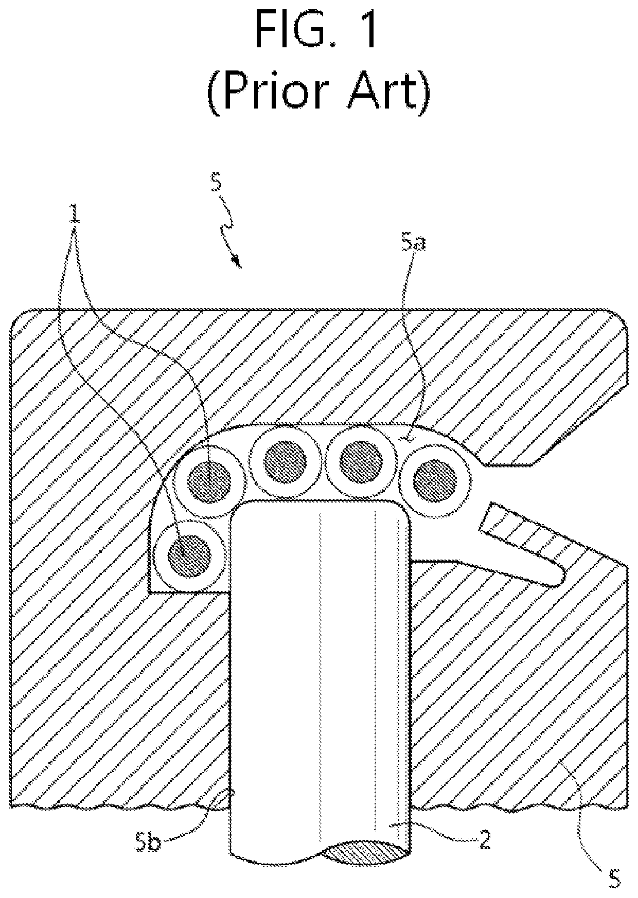
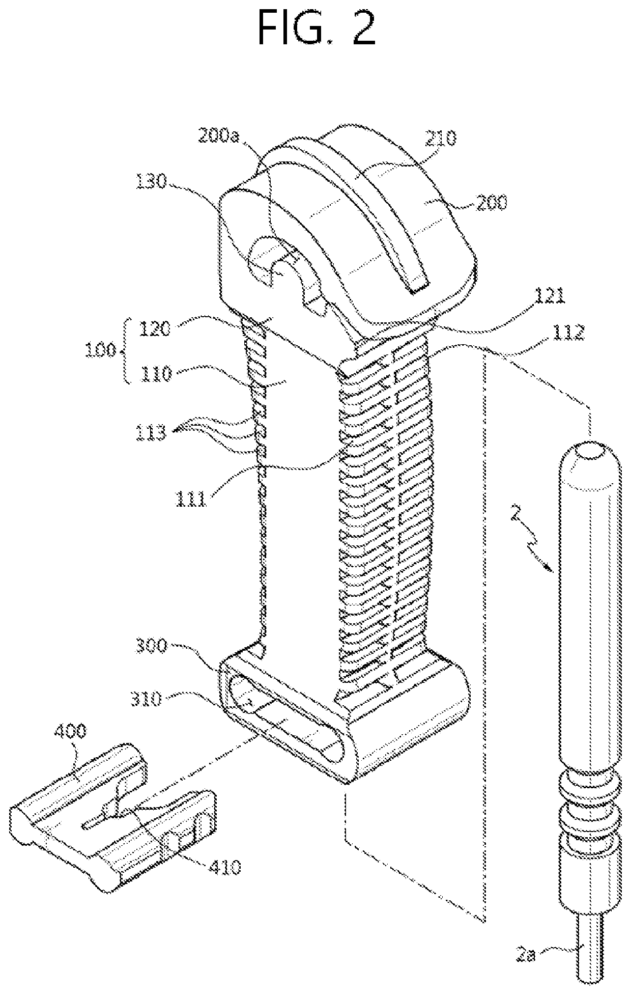
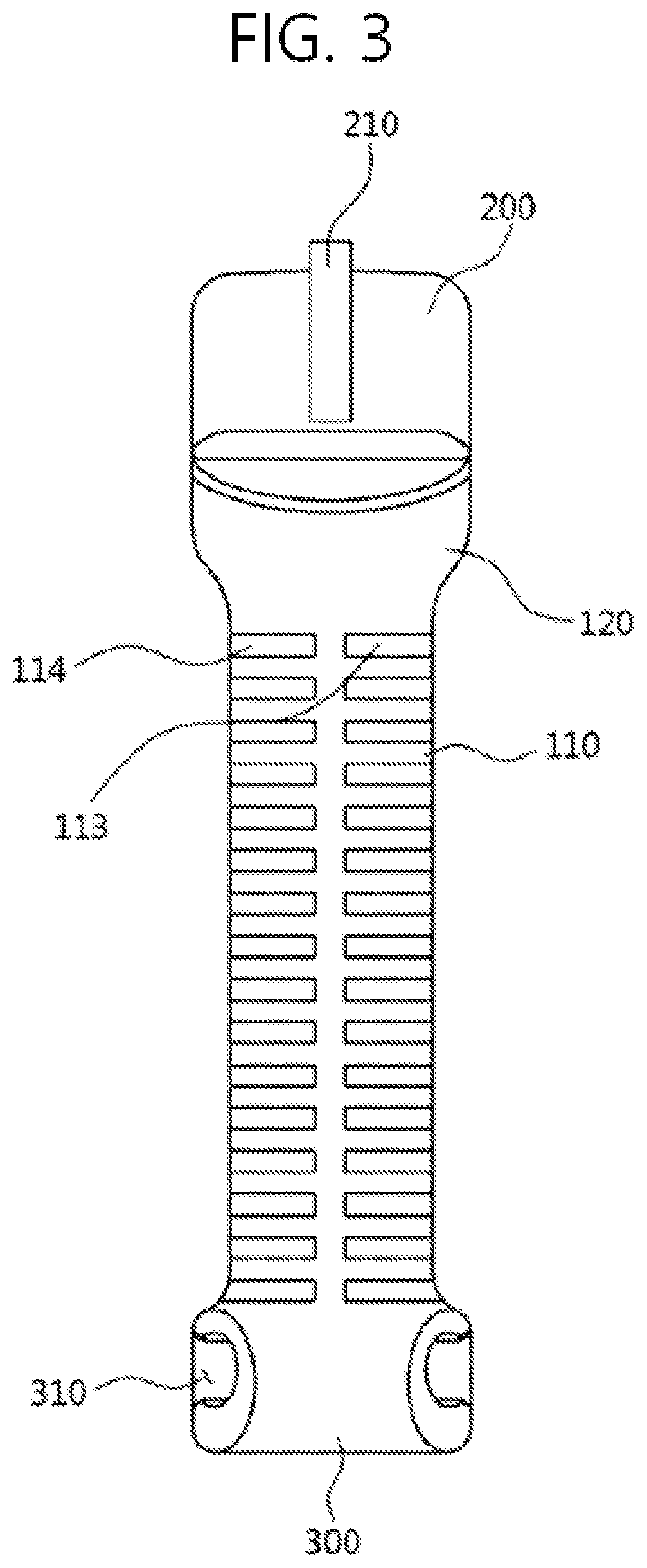
[0039]1: shock tube 2: trunkline delay detonator[0040]100: connector body[0041]101: detonator insertion portion[0042]110: main body member[0043]111: first horizontal groove[0044]112: second horizontal groove[0045]113: third horizontal groove[0046]114: fourth horizontal groove[0047]120: head-supporting member[0048]121: guide protrusion[0049]130: side protrusion for supporting tubes[0050]200: connector head[0051]200a: tube insertion portion[0052]210: head protrusion 300: clip-fixing body[0053]310: clip-fitting portion 400: fixing clip[0054]410: tube-fitting groove

BEST MODE

[0055]Hereinafter, the present disclosure will be described in detail with reference to the accompanying drawings. In the following description, when the detailed description with respect to the functions of conventional elements and the configuration thereof may make the gist of the present disclosure unclear, the detailed description thereof will be omitted. The embodiment of the present disclosure is provided to e...


PUM


Abstract

The present disclosure relates to a connector for a blast-triggering device, said connector including a connector head in which a rear end thereof is integrally connected with a rear surface of a connector body, an upper surface thereof is formed in a curved surface extending from the rear end thereof to a front end thereof, a tube insertion portion is provided between a lower surface thereof and the connector body so that a plurality of shock tubes is fitted therein, and the front end thereof is separated from the connector body. Thus, it is possible to maintain the shape of the connector during detonation, thereby minimizing the generation of debris and improving the safety at the time of detonation. In addition, it is possible to prevent damage to the plurality of shock tubes, thereby preventing a cut-off phenomenon caused by damaged shock tubes during detonation.

Description

TECHNICAL FIELD[0001]The present invention relates to a connector for a blast-triggering device and, more particularly, to a connector for a blast-triggering device configured to minimize scattering of debris during detonation of a detonation, and secure detonation reliability.BACKGROUND ART[0002]Generally, a nonelectric blasting device uses a blast-triggering device in order to simultaneously transmit an explosion signal to a plurality of detonators for igniting an explosive.[0003]That is, the blast-triggering device is configured to simultaneously apply the explosion signal to a plurality of shock tubes connected to the plurality of detonators for igniting an explosive in order to simultaneously detonate the plurality of detonators for igniting the explosive.[0004]The nonelectric blast-triggering device includes: a connector, in which a plurality of shock tubes is fitted; and a trunkline delay detonator, which applies an explosion signal to the shock tubes inserted into the connec...

Claims


Application Information

Patent Timeline
IPC IPC(8): F42D1/00F42D1/04
CPCF42D1/043F42B3/26
Inventor LEE, EUNG SOPARK, KI CHULKIM, SE HUNHA, KYU JIN
Owner HANWHA CORP
Why Eureka
Try Eureka