Valve, especially a damping valve for a vibration damper

Inactive Publication Date: 2005-08-25
ZF FRIEDRICHSHAFEN AG
View PDF5 Cites 0 Cited by
  • Summary
  • Abstract
  • Description
  • Claims
  • Application Information

AI Technical Summary

Benefits of technology

[0007] The task of the present invention is to improve the flow channel ins

Problems solved by technology

Unfavorable flow conditions in a flow channel can generate noise, which it may not be possible to tolerate in certain practical applications.
The funnel shape occupies a comparatively large amount of space, which is often not available in the case of a damping valve for a vibration damper, because otherwise the walls in the area of the damping valve would become too thin.
As a result, noise can be produced, and the lifting behavior of the valve disk can be imprecise.
The attempt has been made to correct these defects by

Method used


Image

  • Valve, especially a damping valve for a vibration damper
  • Valve, especially a damping valve for a vibration damper
  • Valve, especially a damping valve for a vibration damper

Examples


Embodiment Construction

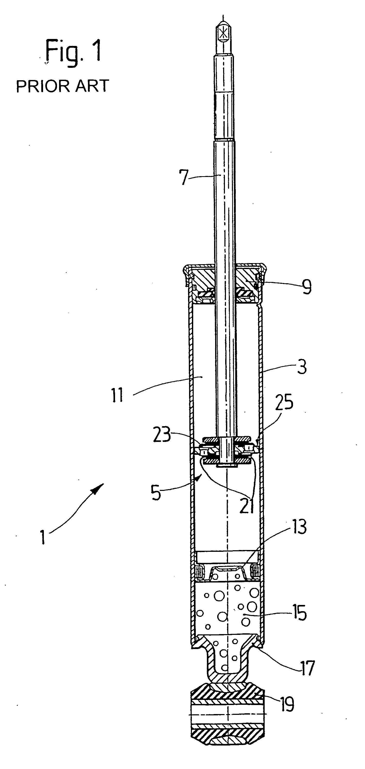
[0021]FIG. 1 shows by way of example a piston-cylinder assembly 1 in the form of a single-tube vibration damper. In principle, the invention can also be applied to other piston-cylinder assemblies.

[0022] The single-tube vibration damper 1 consists essentially of a pressure tube 3, in which a valve body in the form of a piston 5 is mounted on a piston rod 7 with freedom of axial movement. At the outlet end of the piston rod 7, a piston rod guide 9 closes off a damping medium-filled working space 11, which is separated by a separating piston 13 from a gas space 15, which has a bottom piece 17 with an eye 19 at the end.

[0023] When the piston rod moves, damping medium is displaced through damping valves 21 in the piston 5, which are formed by valve disks 23. A piston ring 25, which extends around the circumference of the piston 5, prevents the medium from flowing around the sides of the piston.

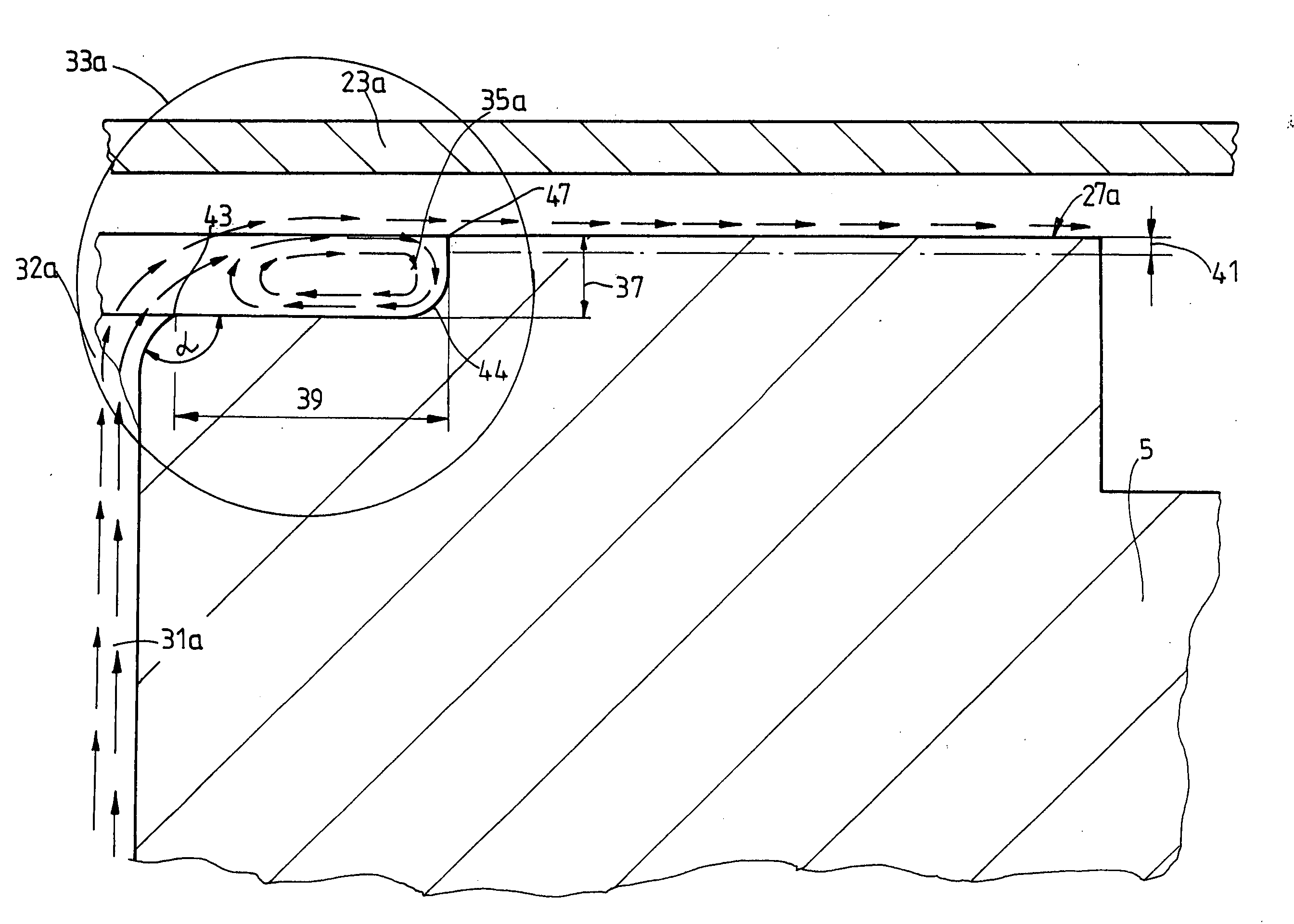
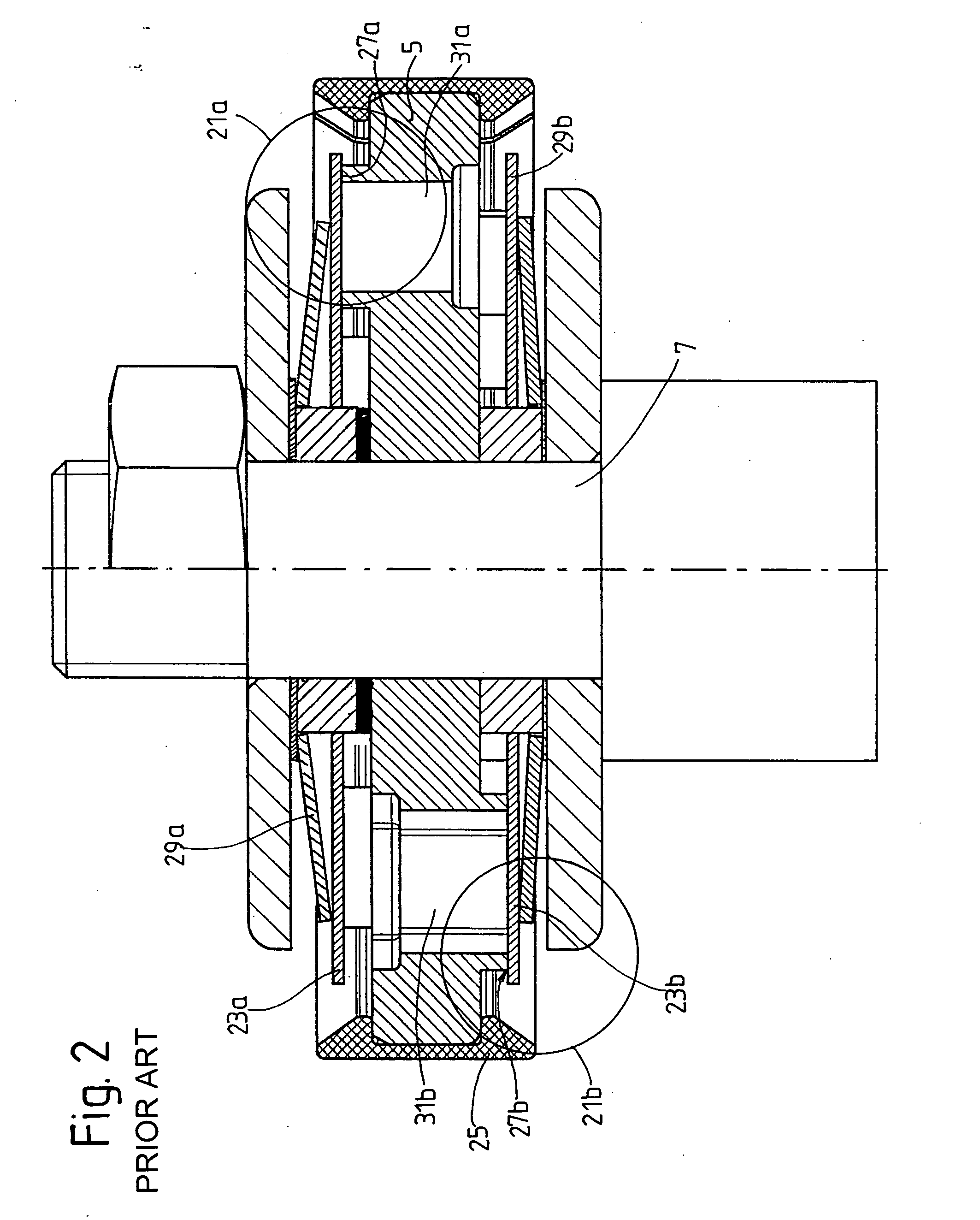
[0024]FIG. 2 shows a detailed view of the piston 5 in the form of a valve body. Damping val...


PUM


Abstract

A damping valve for a vibration damper includes a valve body, which has at least one flow channel with an inlet and outlet, through which a working medium flows from one side to the other side of the valve body, where the inlet and/or the outlet has a cross section which is larger than that of the flow channel. The inlet and/or the outlet has a flow deflection profile, in which a vortex flow is produced, the flow filaments of which form a fluid cushion for the working medium.

Description

BACKGROUND OF THE INVENTION [0001] 1. Field of the Invention [0002] The invention pertains to a damping valve for a vibration damper, including a valve body having a flow channel through which a working medium can flow from one side to the other side of the valve body, the channel having an inlet and an outlet, at least one of the inlet and outlet having a cross-section which is larger than the cross-section of the channel. [0003] 2. Description of the Related Art [0004] A working medium flowing through a valve is subjected to a flow resistance which is determined by, among other things, the geometry of a flow channel. Unfavorable flow conditions in a flow channel can generate noise, which it may not be possible to tolerate in certain practical applications. The flow channels of damping valves are therefore provided with special shapes. U.S. Pat. No. 6,401,755 describes a damping valve for a vibration damper, where the damping valve has a funnel-shaped inlet to and / or outlet from th...

Claims


Application Information

Patent Timeline
IPC IPC(8): F15B21/04F16F9/32F16F9/34F16F9/344F16F9/348F16F9/36F16K15/08F16K47/02
CPCF15B21/008F16F9/3214F16F9/368F16F9/3485F16F9/341Y10T137/7861
Inventor WIRTH, PETERBROOCKS, WILHELM
Owner ZF FRIEDRICHSHAFEN AG
Why Eureka
Try Eureka