
Bumper stopper for a shock absorber

a technology of shock absorber and stopper, which is applied in the direction of shock absorbers, mechanical equipment, transportation and packaging, etc., can solve the problems of increasing the cost and environmental aspect of the shock absorber, and increasing the cost and environmental aspect. , to achieve the effect of minimizing environmental load, reducing manufacturing cost and low cos

Inactive Publication Date: 2014-03-20
HEO YONG HOON +1
View PDF0 Cites 6 Cited by
  • Summary
  • Abstract
  • Description
  • Claims
  • Application Information

AI Technical Summary

Benefits of technology

The present invention introduces a bumper stopper that is cost-effective and environmentally friendly. It is made through injection molding using synthetic resins and can be recycled after use. The bumper stopper is also designed to reduce impact and noise during contraction, improving its durability. Overall, the invention provides a one-stop solution for bumper stopper production, reducing production costs and environmental impact, and improving productivity and durability.

Problems solved by technology

A bumper stopper used in the related shock absorber is manufactured with urethane foam material and as the entire quantity is discarded since it is not recyclable after use and also it has expensive manufacturing cost due to the expensive materials, the problem that it is very unreasonable in cost and environmental aspect is constantly raised.
Also as a dust cover used in the related shock absorber is manufactured separately and is mounted on the shock absorber, the problem, which it not only works as a factor that complicates the manufacturing process of the shock absorber but also works as a factor of cost increase, is pointed out.

Method used


Image

  • Bumper stopper for a shock absorber
  • Bumper stopper for a shock absorber
  • Bumper stopper for a shock absorber

Examples


Embodiment Construction

[0026]Hereinafter, aspects of the present disclosure will be described in detail with reference to the accompanying drawings. In the following description, the same elements will be designated by the same reference numerals although they are shown in different drawings. Further, in the following description of the present disclosure, a detailed description of known functions and configurations incorporated herein will be omitted when it may make the subject matter of the present disclosure rather unclear.

[0027]Additionally, in describing the components of the present disclosure, there may be terms used like first, second, A, B, (a), and (b). These are solely for the purpose of differentiating one component from the other but not to imply or suggest the substances, order or sequence of the components. If a component were described as ‘connected’, ‘coupled’, or ‘linked’ to another component, they may mean the components are not only directly ‘connected’, ‘coupled’, or ‘linked’ but als...


PUM

PropertyMeasurementUnit
Lengthaaaaaaaaaa

Abstract

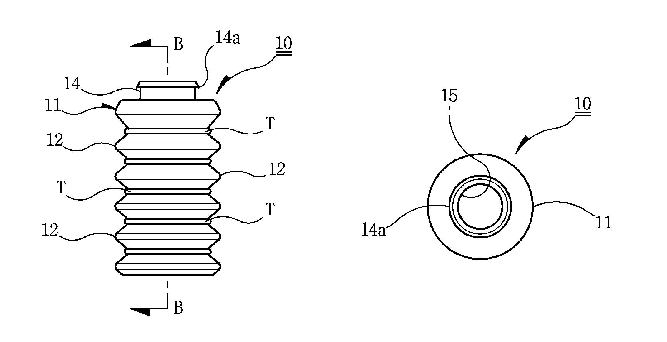
A shock absorber for a bump stopper includes a plurality of corrugated projection 12 and corrugated groove 13 which is formed in equal interval around outside of an elastic synthetic resin body 11 having a thickness of 1.5 mm˜5 mm; a locking member 14 formed to mount the shock absorber on the top of the body 11; a through hole 15 formed inside the locking member 14; a leading hole 17 formed to lead cylinder lot L in the central part of a shock absorbing plate 16 forming the lower side of the body 11; a wedge hanging projection 14a formed in the locking member 14 of the body; and an O-ring shock absorbing member T to ease the impact applied to a bent part R in contraction of a body 11, in a “<” or “>”-type bent part R.

Description

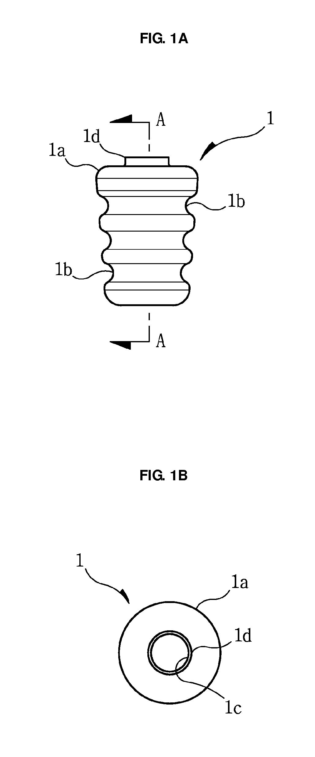
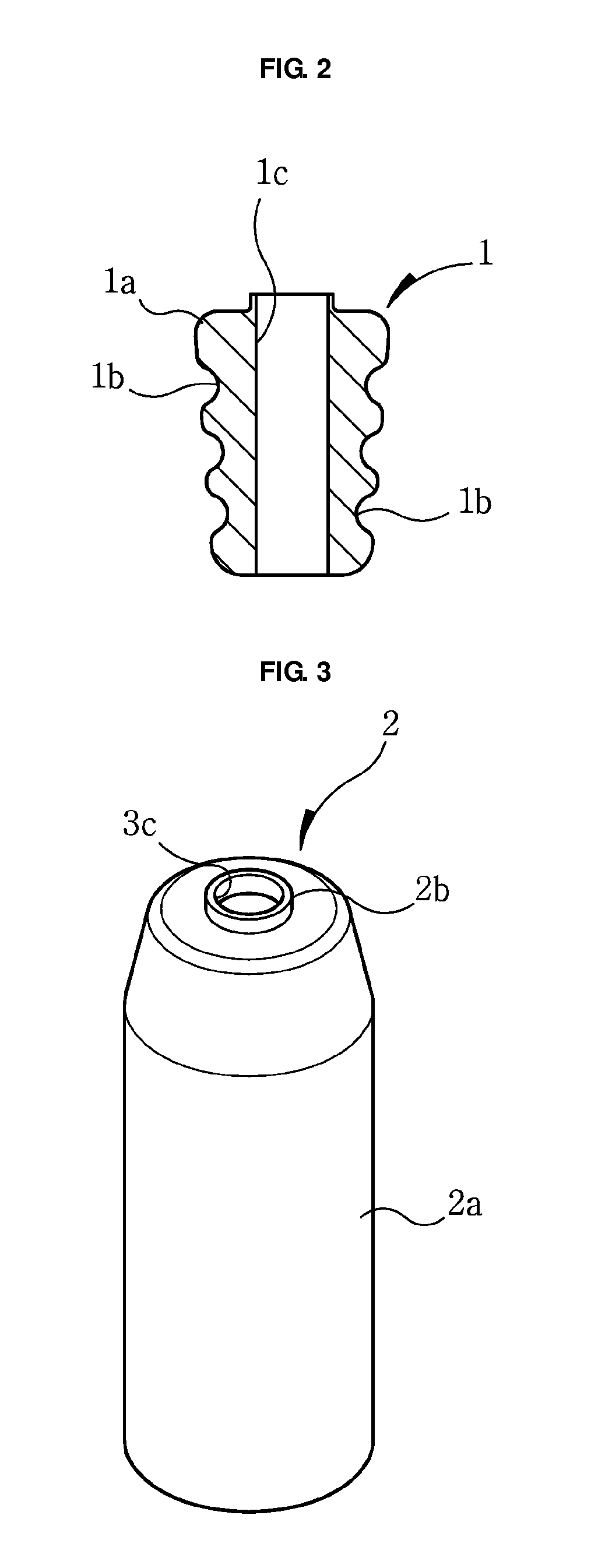
TECHNICAL FIELD[0001]The present invention relates to a bumper stopper for a shock absorber. More particularly, the present invention is a shock absorber used as a vehicle shock absorber and is to provide a bumper stopper which is used to deal with impact of cylinder ascending / descending according to the running state of a vehicle.BACKGROUND ART[0002]In vehicle, yawing, vibration, and impact according to the curve and slope of road, acceleration and brake, turn, etc pass from various direction, and a shock absorber is used as means to control a vehicle stable in such vibration or yawing.[0003]The shock absorber is embodied by a combination of cylinder which fills oil or gas and a coil-type spring which covers the cylinder, and a bumper stopper which deals with impact of cylinder and a dust cover which protects the cylinder from dust or other impurities are comprised in components of shock absorber.[0004]An example of a related bumper stopper 1 is illustrated in FIG. 1 and cross sect...

Claims


Application Information

Patent Timeline
IPC IPC(8): B60G11/22
CPCB60G15/065B60G2202/143B60G2202/312B60G2204/125B60G2204/45021B60G2206/71044B60G2206/81012F16F9/38F16F9/58
Inventor HEO, YONG-HOONKIM, YOUNG-CHUN
Owner HEO YONG HOON
Learn More