
Crank apparatus, bicycle and stationary exercise bicycle
a crank apparatus and stationary exercise technology, applied in gymnastic exercise, apparatus for force/torque/work measurement, instruments, etc., can solve the problems of inconvenience for users, insufficient change amount of strain characteristic obtained by strain gauge, etc., to improve measuring accuracy and increase convenience for users
- Summary
- Abstract
- Description
- Claims
- Application Information
AI Technical Summary
Benefits of technology
Problems solved by technology
Method used
Image

Examples
Embodiment Construction
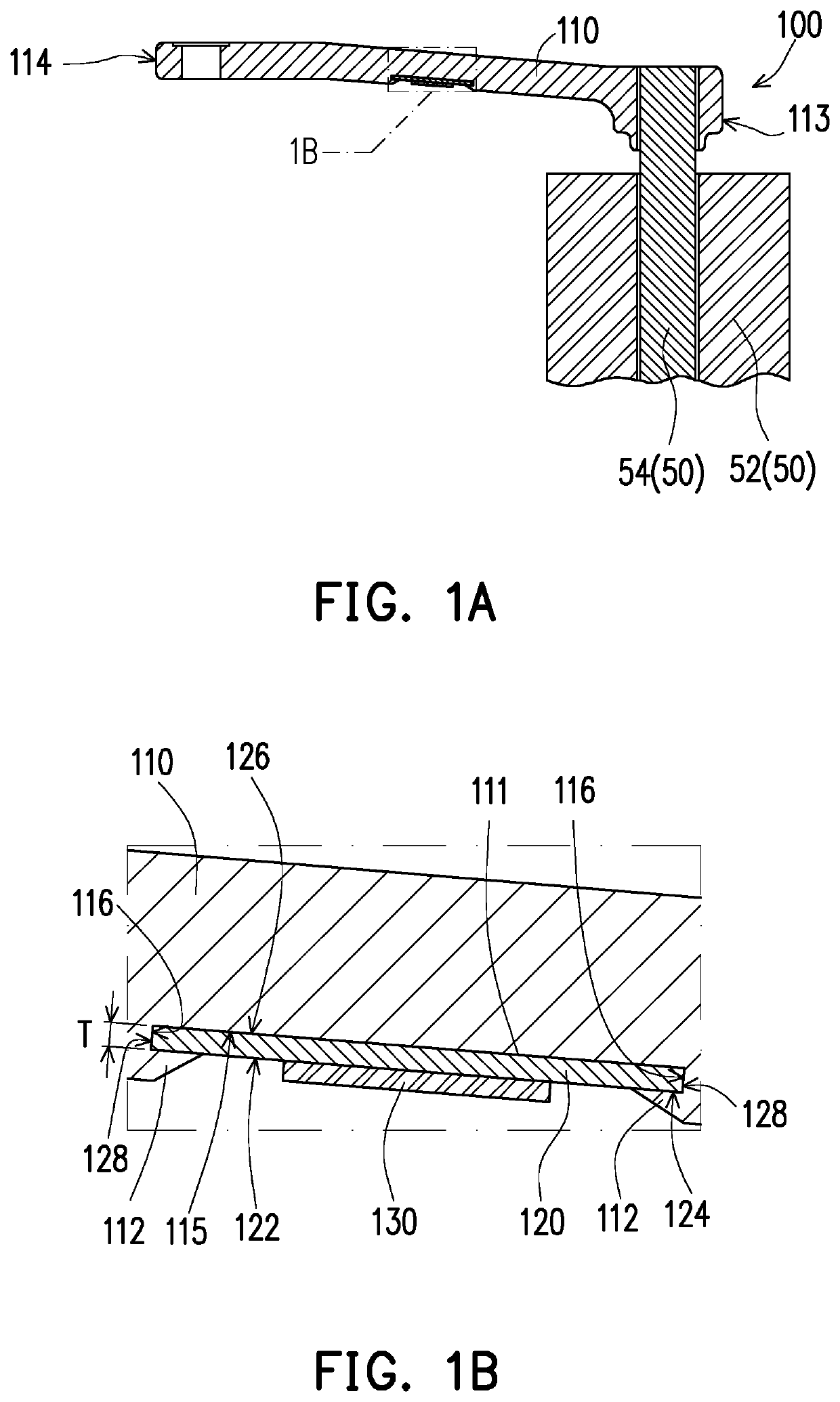
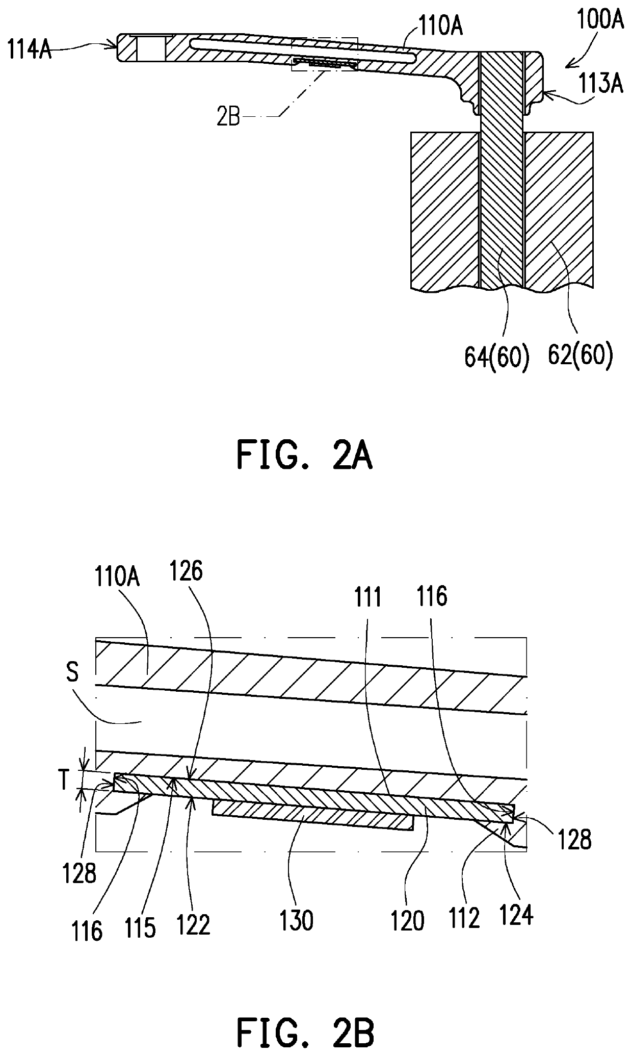
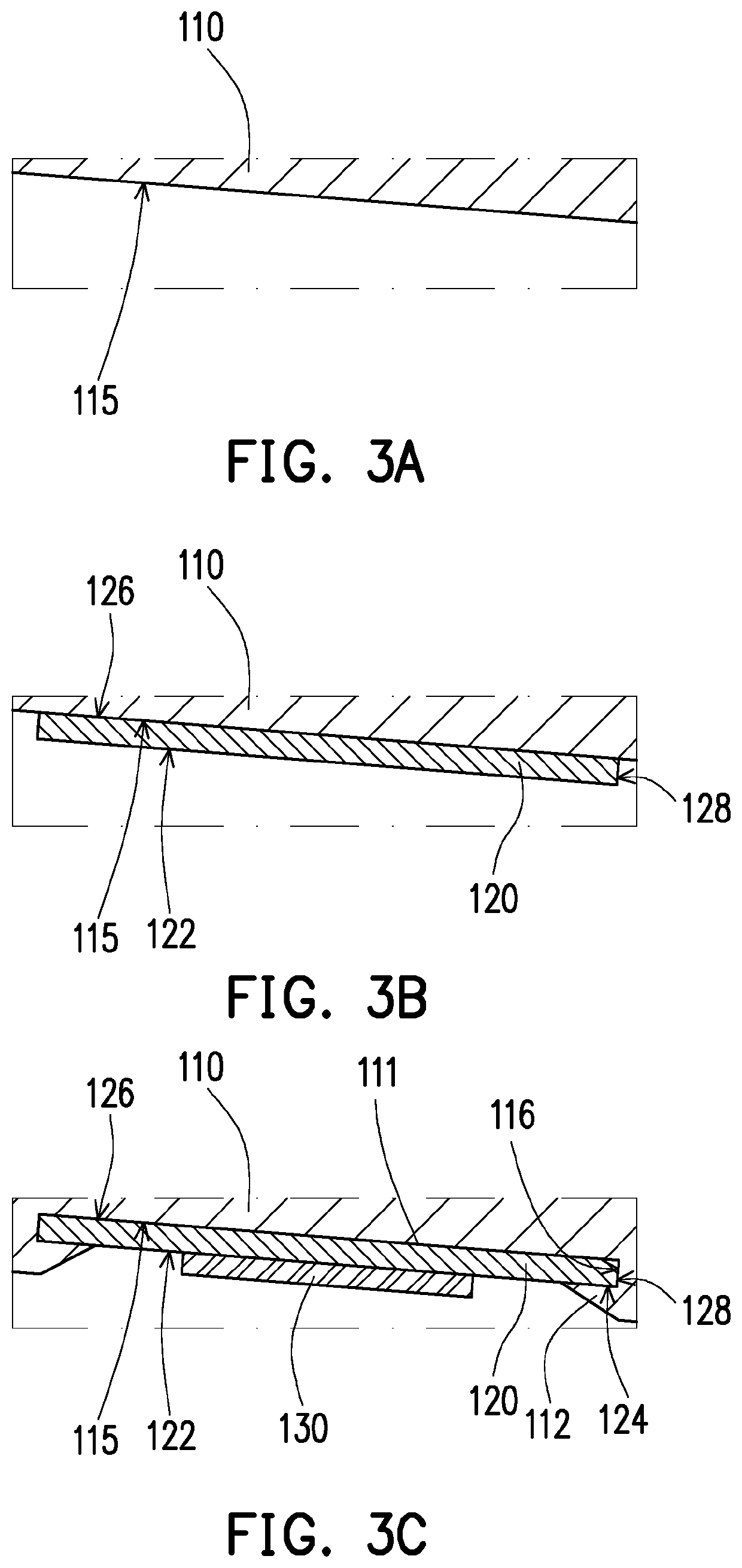
[0045]FIG. 1A is a schematic cross-sectional view of a crank apparatus according to an embodiment of the disclosure. FIG. 1B is an enlarged view of the portion, labeled ‘1B’ of FIG. 1A. Referring to FIG. 1A and FIG. 1B, a crank apparatus 100 includes a crank arm 110, at least one thin material layer 120 and at least one sensing element 130. The crank arm 110 can be formed with at least one cavity 111 on at least one of the surfaces in the manufacturing process, and the cavity 111 can be communicated with the outer environment. The thin material layer 120 is embedded into the cavity 111, and the thin material layer 120 having an exposed outer surface 122. The sensing element 130 is attached to the outer surface 122 exposed by the thin material layer 120. The crank arm 110 is manufactured of a material having non-uniform strain characteristic. The thin material layer 120 is manufactured of a material having uniform strain characteristic. The crank arm 110 may be deformed by being subj...
PUM
| Property | Measurement | Unit |
|---|---|---|
| thickness | aaaaa | aaaaa |
| thickness | aaaaa | aaaaa |
| angle | aaaaa | aaaaa |
Abstract
Description
Claims
Application Information