
Display panel with asymmetrically disposed pads

a technology of asymmetrical asymmetry and pads, applied in the field of display panels, can solve the problems of not being conductive to narrow the borders of products, and achieve the effects of reducing the edge width of the display panel, optimizing the arrangement space of the pads, and increasing the screen-to-body ratio of the display panel

Active Publication Date: 2021-10-05
WUHAN CHINA STAR OPTOELECTRONICS SEMICON DISPLAY TECH CO LTD
View PDF17 Cites 0 Cited by
  • Summary
  • Abstract
  • Description
  • Claims
  • Application Information

AI Technical Summary

Benefits of technology

[0006]The present invention provides a display panel which is able to reduce the routing area, reduce the width of the boarder of the display panel and improve the screen-to-body ratio.
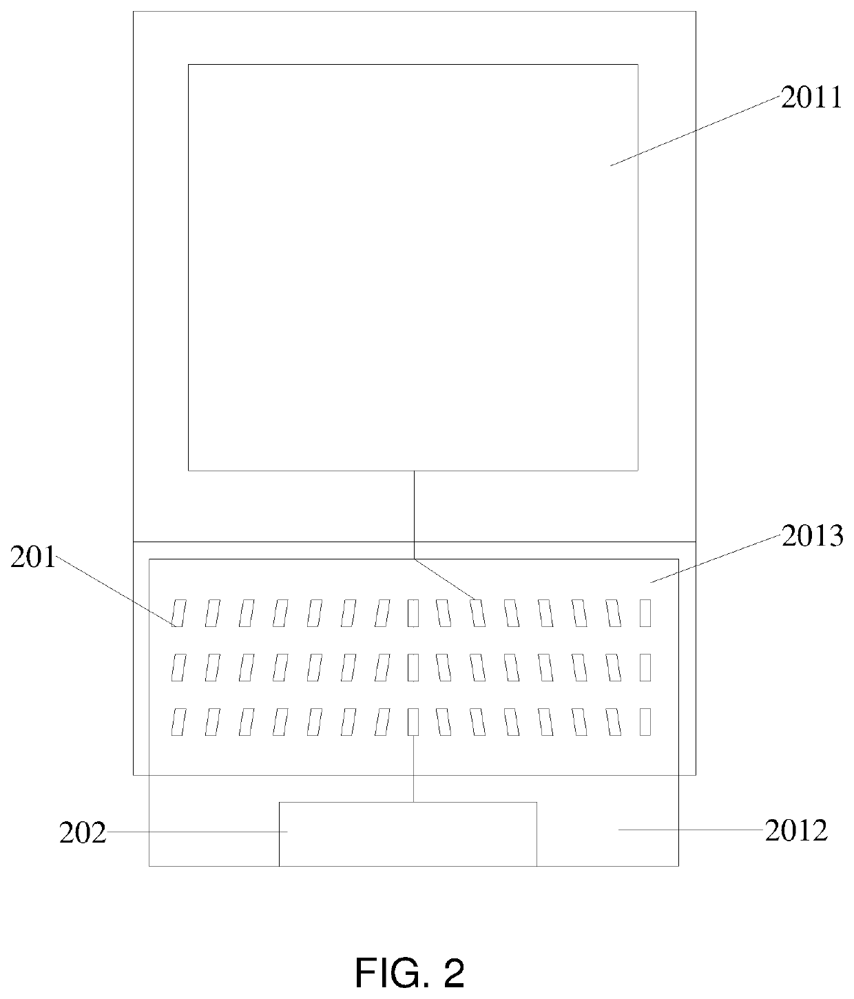
[0023]The beneficial effect of the present invention is that the display panel provided by the embodiment of the present invention comprises a display area, a binding area and a pad area located between the display area and the binding area, the display area provided with a function layer, the binding area provided with a driving unit, wherein the pad area provided with a plurality of pads arranged in multiple rows and multiple columns, one end of each of the pads is connected to the function layer, the other end of each of the pads is connected to the driving unit, wherein the plurality of pads are disposed asymmetrically with respect to a centerline, and the centerline is a centerline of the display panel running through the display area, the pad area and the binding area. The display panel of the present invention greatly optimizes the arrangement space of the pads to reduce the edge width of the display panel by arranging the pads in multiple rows and multiple columns, it can increase the screen-to-body ratio of the display panel. Furthermore, each of pitches between columns of the pads is the same, it can optimize the way of the routing between the pads to reduce the routing length that the pads are connected to the display area, and increase the stability of the driving signal to improve the display effect of the display panel simultaneously.

Problems solved by technology

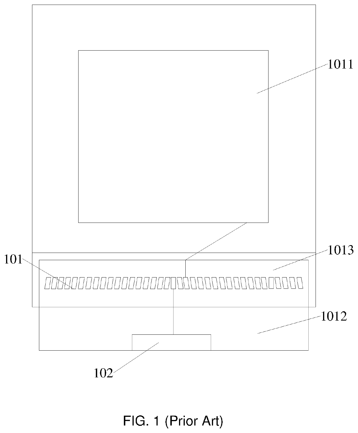
However, a large amount of space is occupied by the routing that the existing pads are connected to the display area, it is not conductive to narrow the borders of products.

Method used


Image

  • Display panel with asymmetrically disposed pads
  • Display panel with asymmetrically disposed pads
  • Display panel with asymmetrically disposed pads

Examples


first embodiment

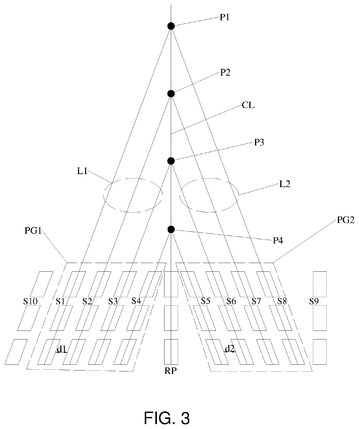
[0046]In the display panel provided by the present invention, the pads are arranged in multiple rows and multiple columns. Multiple columns of the pads are disposed symmetrically with respect to the centerline, and the centerline divides the symmetrically-disposed pads into two groups of the pads located at two sides of the centerline. Each of pitches between columns of the pads in each of groups is the same, the routing distance between the pads in each of columns is widened, and the routing length that the pads are connected to the display area decrease. It can reduce the edge width of the display panel, increase the screen-to-body ratio, and increase the stability of the driving signal to improve the display effect of the display panel simultaneously.

[0047]FIG. 4 is a schematic planar diagram showing an arrangement of pads in the display panel in accordance with the second embodiment of the present invention. In the display panel provided by the first embodiment of the present in...

second embodiment

[0058]In the display panel provided by the present invention, the pads are divided into two pad groups located at two sides of the centerline. Each of extension lines of groups of the pads is intersected with the centerline, and each of extension lines of columns of the pads in the same group is intersected at the same point. Multiple columns of the pads in each of groups are disposed with a certain angle toward a direction that is parallel to the centerline CL. It can effectively optimize the arrangement of the pads, reduce the width of the edge of the display panel, and improve the screen-to-body ratio.

[0059]The beneficial effect of the present invention is that the display panel provided by the embodiments of the present invention includes a display area, a binding area, and a pad area located between the display area and the binding area. The display area is provided with a function layer, the binding area is provided with a driving unit, and the pad area is provided with a plur...


PUM


Abstract

The present invention provides a display panel, including a display area, a binding area and a pad area located between the display area and the binding area. The display area is provided with a function layer, the binding area is provided with a driving unit, and the pad area provided with a plurality of pads arranged in multiple rows and multiple columns. One end of each of the pads is connected to the function layer, and the other end of each of the pads is connected to the driving unit, wherein the plurality of the pads are disposed asymmetrically with respect to the centerline, and the centerline is a centerline of the display panel running through the display area, the pad area, and the binding area.

Description

CROSS REFERENCE[0001]The application claims the priority of International Application No. PCT / CN2019 / 117913, filed on Nov. 13, 2019, titled “DISPLAY PANEL”, which claims priority to Chinese Application NO. 201910664133.1, filled on Jul. 23, 2019. The entire disclosures of each of the applications are incorporated herein by reference.FIELD OF INVENTION[0002]The invention relates to a field of display technology, and more particularly to a display panel.BACKGROUND OF INVENTION[0003]Full-screen mobile phones are getting more and more popular. Screens with a high screen-to-body ratio become more and more popular. The so-called screen-to-body ratio is a ratio of a screen area to an area of whole mobile phone. Higher screen-to-body ratio may give user a better visual experience. The display effect of the full-screen display performs better with a higher screen-to-body ratio. Therefore, the full-screen display has favorited by more and more consumers and has become an inventible trend of t...

Claims


Application Information

Patent Timeline
Patent Type & Authority Patents(United States)
IPC IPC(8): H01L27/32G09G3/3225
CPCH01L27/3276G09G3/3225G09G3/20G09G2300/0426G09G3/035H10K59/131
Inventor TSAI, KUNYUEH
Owner WUHAN CHINA STAR OPTOELECTRONICS SEMICON DISPLAY TECH CO LTD
Learn More