Walking training apparatus and walking training method therefor

a training apparatus and walking technology, applied in the field of walking training apparatus, can solve the problems of preventing the user from doing a stable walking training, affecting the stability of walking training, and excessive load on the leg, and achieve the effect of reducing the load

Active Publication Date: 2021-10-12
TOYOTA JIDOSHA KK
View PDF18 Cites 1 Cited by
  • Summary
  • Abstract
  • Description
  • Claims
  • Application Information

AI Technical Summary

Benefits of technology

[0007]The present disclosure has been made in view of the above-described problems and one of the main objects thereof is to provide a walking training apparatus and a walking training method therefor capable of reducing the load exerted on a leg to which a walking assistance apparatus is attached at the start of swinging of that leg or during the swinging period thereof.
[0008]A first exemplary aspect of the present disclosure is a walking training apparatus includes a walking assistance apparatus attached to a leg of a user, the walking assistance apparatus being configured to assist the user to walk, a first pulling mechanism to pull the leg upward and forward directly or through the walking assistance apparatus, and a controller configured to control the first pulling mechanism so that a vertically-upward component of a pulling force applied by the first pulling mechanism reduces a weight of the walking assistance apparatus. The walking training apparatus further includes at least one of a joint angle detector disposed in the walking assistance apparatus and an image pickup device to take an image of the leg of the user. The controller is configured to make the first pulling mechanism generate an additional pulling force in addition to the pulling force at a start of forward swinging of the leg or during a swinging period of the leg in a walking motion of the user, by using information detected by at least one of the joint angle detector and the image pickup device. According to this aspect, the load exerted on the leg to which the walking assistance apparatus is attached can be reduced at the start of swinging of that leg or during the swinging period thereof.
[0009]In an aspect, the walking training apparatus may further include a second pulling mechanism to pull the leg upward and backward directly or through the walking assistance apparatus. The controller may be configured to control the first and second pulling mechanisms so that a resultant force of vertically-upward components of pulling forces applied by the first and second pulling mechanisms reduces the weight of the walking assistance apparatus, and control the first and second pulling mechanisms so that the first and second pulling mechanisms generate an additional pulling force in addition to the resultant force at the start of forward swinging of the leg or during the swinging period of the leg in the walking motion of the user, by using information detected by at least one of the joint angle detector and the image pickup device. According to this aspect, the vertically-upward components and the horizontally-forward components of the pulling forces applied by the first and second pulling mechanisms can be accurately controlled independently of each other. As a result, it is possible to, while reducing the load caused by the gravitational force of the walking assistance apparatus, reduce the load exerted on the leg to which the walking assistance apparatus is attached at the start of swinging of that leg or during the swinging period thereof in a more optimal manner.

Problems solved by technology

However, although the above-described walking training apparatus reduces the load on user's walking caused by the gravitational force of the walking assistance apparatus, it does not reduce the above-described load caused by the inertial force.
Therefore, an excessive load is exerted on the leg to which the walking assistance apparatus is attached at the start of swinging of that leg.
However, in such a case, the leg could be easily lifted inadvertently, making the landing of the leg unstable and preventing the user from doing a stable walking training.

Method used


Image

  • Walking training apparatus and walking training method therefor
  • Walking training apparatus and walking training method therefor
  • Walking training apparatus and walking training method therefor

Examples


Embodiment Construction

[0023]Exemplary embodiments according to the present disclosure are explained hereinafter with reference to the drawings.

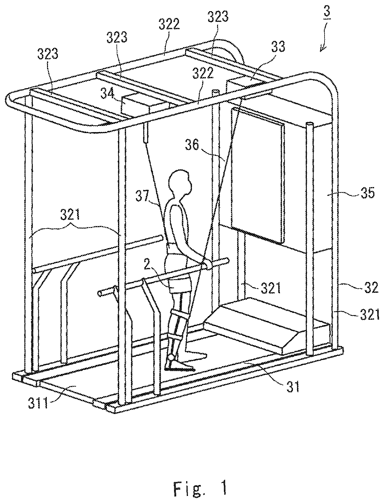
[0024]FIG. 1 is a perspective view showing a schematic configuration of a walking training apparatus according to an exemplary embodiment of the present disclosure. A walking training apparatus according to this exemplary embodiment is, for example, an apparatus by which a user such as a patient having hemiplegia caused by a stroke does a walking training. The walking training apparatus includes a walking assistance apparatus 2 attached to the user's leg and a training apparatus 3 by which the user does a walking training.

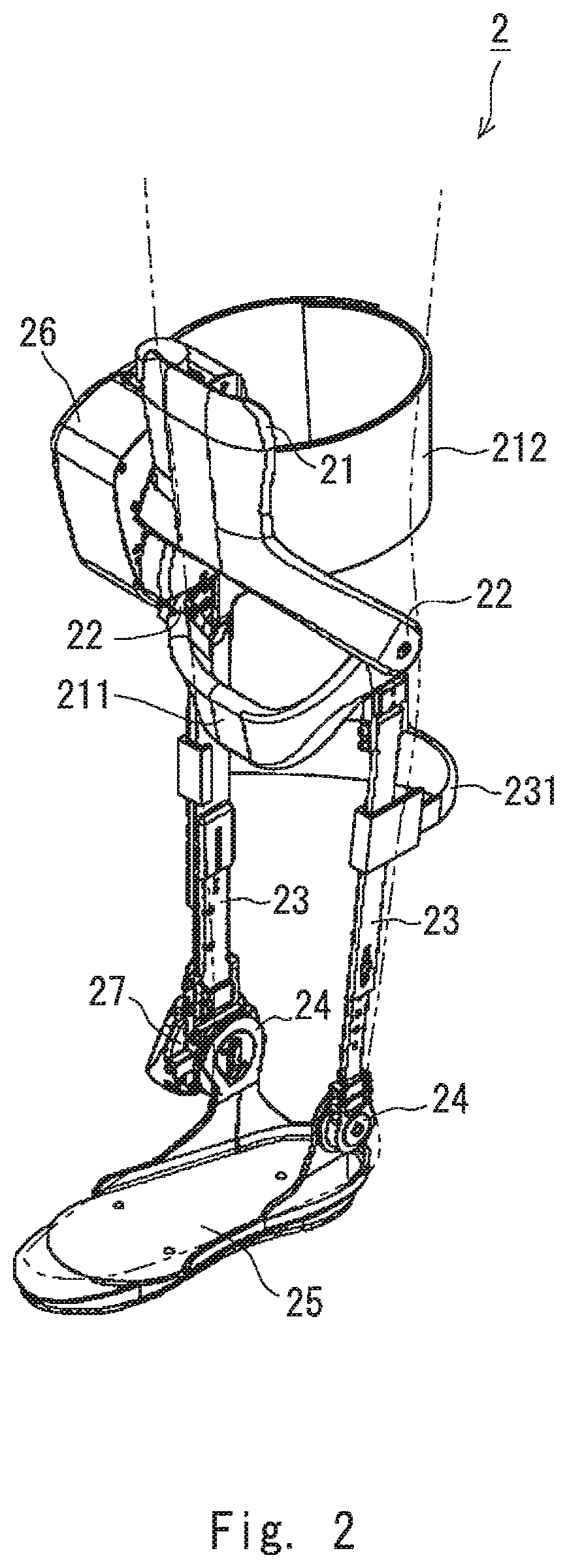
[0025]The walking assistance apparatus 2 is, for example, attached to a diseased leg of a user who does a walking training and assists walking of the user (FIG. 2). The walking assistance apparatus 2 includes an upper thigh frame 21, a lower thigh frame 23 connected to the upper thigh frame 21 through a knee joint part 22, a sole frame 25 connect...


PUM


Abstract

A walking training apparatus includes a walking assistance apparatus attached to a leg of a user, a first pulling mechanism to pull the leg upward and forward, a controller configured to control the first pulling mechanism so that a vertically-upward component of a pulling force applied by the first pulling mechanism reduces a weight of the walking assistance apparatus, and a joint angle detector disposed in the walking assistance apparatus or an image pickup device to take an image of the leg of the user. The controller is configured to make the first pulling mechanism generate an additional pulling force in addition to the pulling force at a start of forward swinging of the leg or during a swinging period of the leg in a walking motion of the user, by using information detected by at least one of the joint angle detector and the image pickup device.

Description

CROSS-REFERENCE TO RELATED APPLICATIONS[0001]This application is based upon and claims the benefit of priority from Japanese patent application No. 2015-157349, filed on Aug. 7, 2015, the entire contents of which are incorporated herein by reference in entirety.BACKGROUND OF THE DISCLOSURE[0002]1. Field of the Disclosure[0003]The present application relates to a walking training apparatus by which a user does a walking training and a walking training method therefor.[0004]2. Description of Related Art[0005]For example, the applicant of the present application has proposed a walking training apparatus including a walking assistance apparatus that is attached to a leg of a user and assists walking performed by the user (see Japanese Unexamined Patent Application Publication No. 2015-223294).[0006]Here, assume a configuration in which first pulling means for pulling one of the walking assistance apparatus and a user's leg upward and forward, and second pulling means for pulling one of ...

Claims


Application Information

Patent Timeline
Patent Type & Authority Patents(United States)
IPC IPC(8): A61H3/00A63B24/00A63B22/02A61H1/02A63B21/00A63B22/00A63B23/035A63B69/00G06K9/00
CPCA61H3/008A61H1/0262A61H3/00A63B21/00181A63B21/4035A63B22/0046A63B22/0087A63B22/02A63B22/0235A63B23/03516A63B24/0087A63B69/0057G06K9/00342A61H2201/1215A61H2201/1481A61H2201/165A61H2201/1621A61H2201/1642A61H2201/1652A61H2201/5007A61H2201/5069A61H2205/10A63B21/153A63B69/0062A63B2022/0094A63B2209/10A63B2220/05A63B2220/16A63B2220/34A63B2220/803A61B5/0077A61B5/1118A61B5/112A61H2003/007A61H2003/005A61H2201/14A61H2201/1261A61H2201/1657G06V40/23A63B21/4011A63B2220/833A63B2220/806A63B2220/30Y10S482/901
Inventor SUGATA, HIKARU
Owner TOYOTA JIDOSHA KK
Why Eureka
Try Eureka