Dual-shaft hinge module and portable electronic device

a dual-shaft, electronic device technology, applied in the direction of hinges, wing accessories, instruments, etc., can solve the problems of limited space of the fixed hinge module, inability to meet the usage requirements of having additional accessories, and inability to adapt to the general usage state of the hinge modul

Active Publication Date: 2021-10-12
COMPAL ELECTRONICS INC
View PDF22 Cites 3 Cited by
  • Summary
  • Abstract
  • Description
  • Claims
  • Application Information

AI Technical Summary

Benefits of technology

[0005]The disclosure provides a dual-shaft hinge module and a portable electronic device, wherein the dual-shaft hinge module can provide an adjustable shaft wheelbase and allows different bodies of the portable electronic device to be synchronously rotated.
[0016]Based on the above, the dual-shaft hinge module disposes a gear set between the first shaft and the second shaft, wherein the first driving gear of the gear set is disposed on the first shaft, the second driving gear is disposed on the second shaft, and the driven gears of the gear set are coupled between the first driving gear and the second driving gear, so that the first driving shaft and the second driving shaft can achieve the effect of synchronous rotation through the gear set. Furthermore, any two engaged gears of the gear set are further respectively pivoted through the links, such that the any two engaged gears can also keep the center distance fixed during the process of synchronous rotation. Accordingly, the gear set can adjust the relative distance of the first shaft and the second shaft according to the requirements under the limitation of the links.
[0017]In this way, for the dual-shaft hinge module or the portable electronic device applying the dual-shaft hinge module, the relative distance between the shafts or the relative distance between the bodies can be adjusted accordingly, thereby providing additional space for utilization, such that the freed up space of the body can accommodate another additional accessory.

Problems solved by technology

However, for conventional hinge modules, the wheelbase between shafts is fixed, so the conventional hinge modules can only cope with the general usage state.
Once the additional accessory is added as described above, there will be space limitation to the fixed hinge module.
In other words, in the case where the body of the hinge module with fixed wheelbase has a fixed space correspondence relationship, it is difficult to meet the usage requirements of having additional accessories.

Method used


Image

  • Dual-shaft hinge module and portable electronic device
  • Dual-shaft hinge module and portable electronic device
  • Dual-shaft hinge module and portable electronic device

Examples


Embodiment Construction

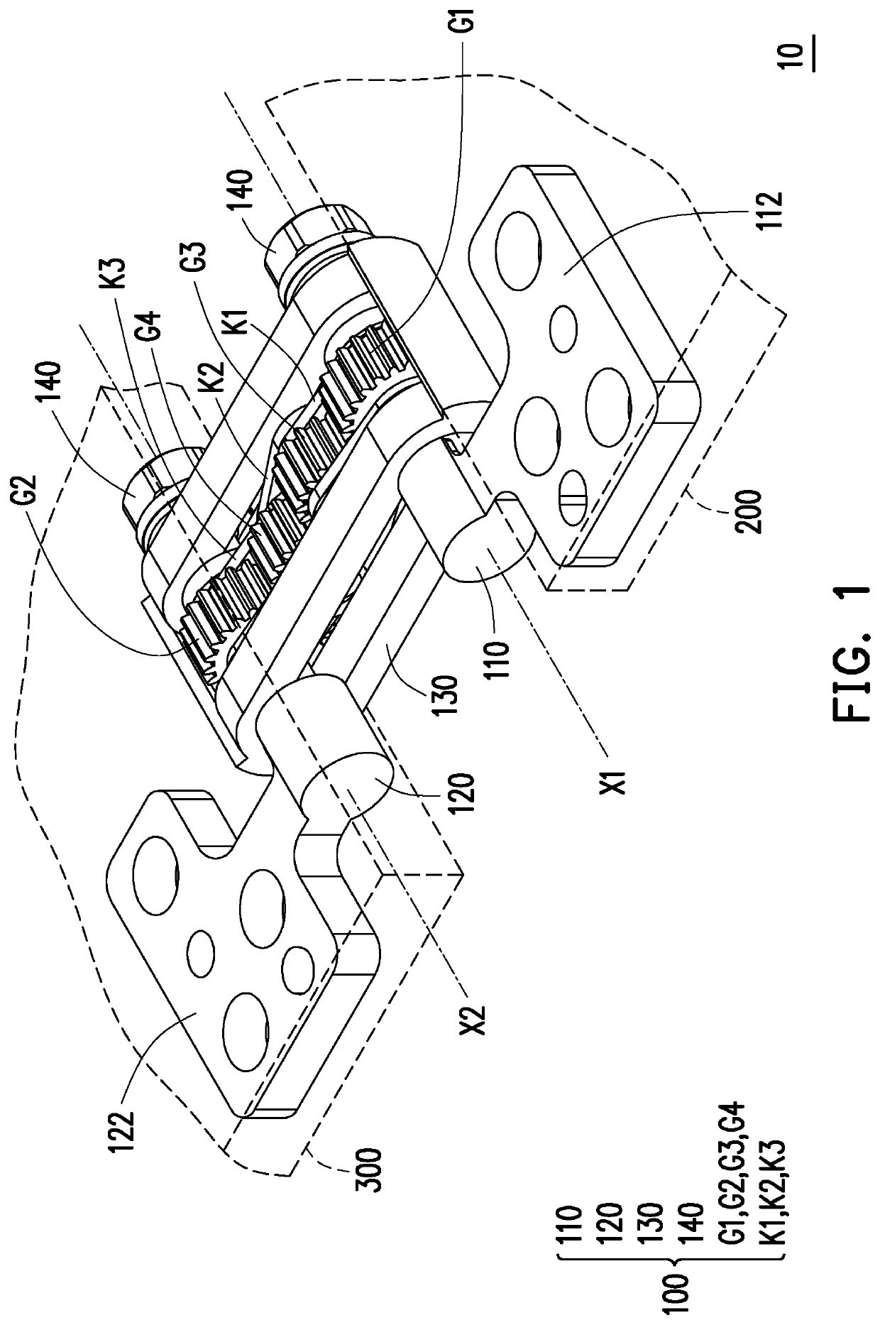
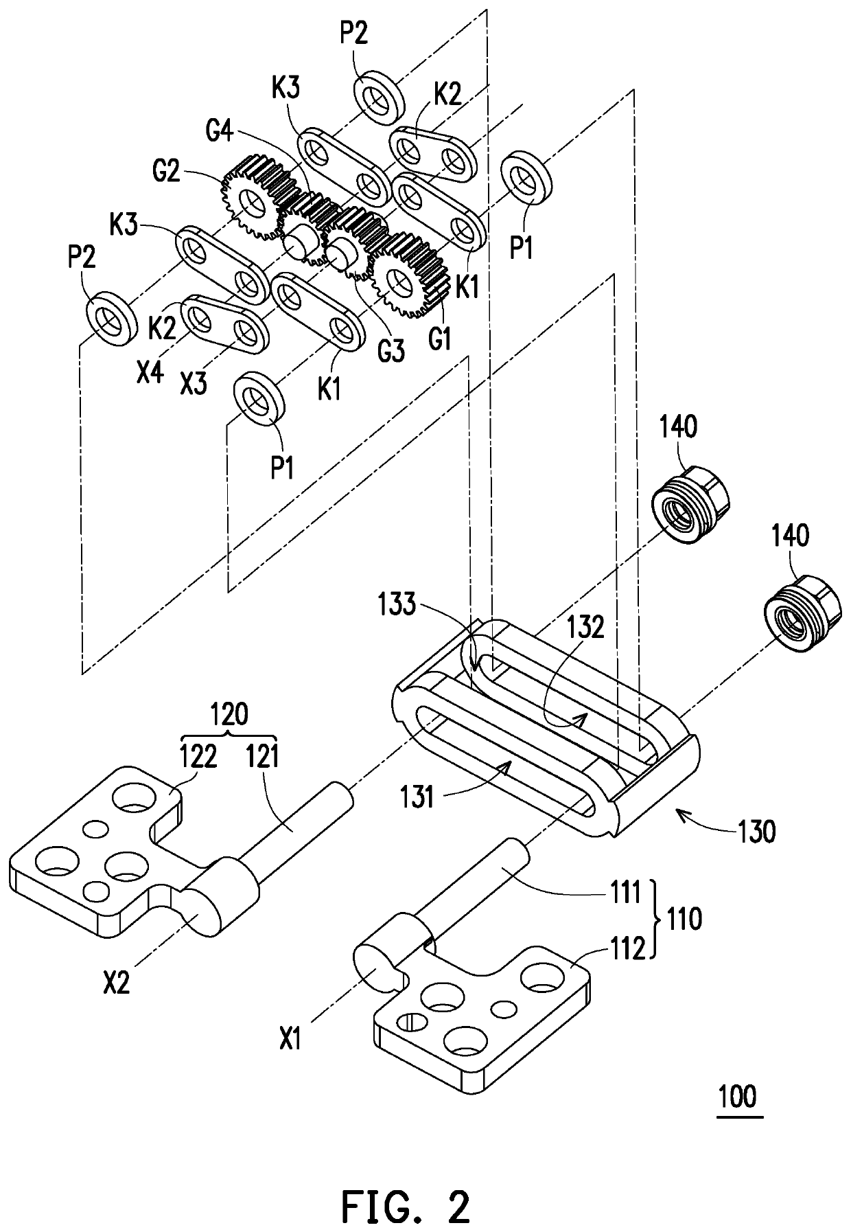
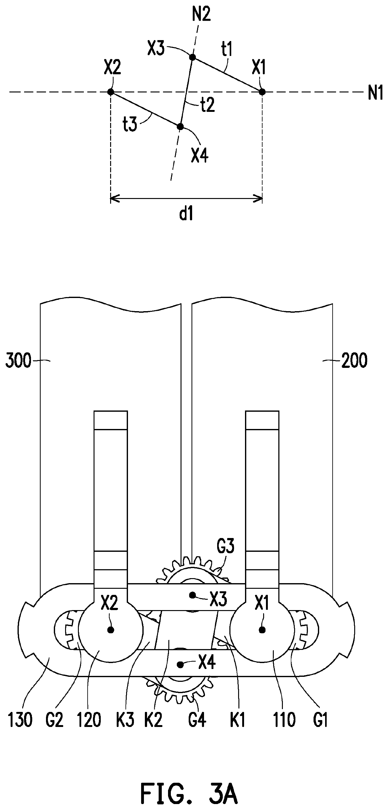
[0023]FIG. 1 is a schematic view of a portion of a portable electronic device according to an embodiment of the disclosure. FIG. 2 is an exploded view of a dual-shaft hinge module of FIG. 1. Please refer to FIG. 1 and FIG. 2 at the same time. In the embodiment, a portable electronic device 10 includes a first body 200, a second body 300, and a dual-shaft hinge module 100, wherein the dual-shaft hinge module 100 includes a first shaft 110, a first driving gear G1, a second shaft 120, a second driving gear G2, a pair of driven gears G3 and G4, and multiple links K1 to K3. The first shaft 110 includes a shaft portion 111 and a bracket 112. The bracket 112 is assembled to the first body 200 and the first driving gear G1 is disposed on the shaft portion 111. The second shaft 120 includes a shaft portion 121 and a bracket 122. The bracket 122 is assembled to the second body 300 and the second driving gear G2 is disposed on the shaft portion 121. The driven gears G3 and G4 are coupled betw...


PUM


Abstract

A dual-shaft hinge module including a first shaft, a first driving gear disposed on the first shaft, a second shaft, a second driving gear disposed on the second shaft, a pair of driven gears coupled between the first driving gear and the second driving gear, and multiple links is provided. The links are respectively pivoted to any two engaged gears to keep a center distance of the engaged gears fixed. A relative distance of the first shaft and the second shaft is changed along with different engagement positions of the driven gears relative to the first driving gear and the second driving gear. A portable electronic device is also provided.

Description

CROSS-REFERENCE TO RELATED APPLICATION[0001]This application claims the priority benefit of U.S. provisional application Ser. No. 62 / 817,509, filed on Mar. 12, 2019. The entirety of the above-mentioned patent application is hereby incorporated by reference herein and made a part of this specification.BACKGROUNDTechnical Field[0002]The disclosure relates to a hinge module and an electronic device, and more particularly to a dual-shaft hinge module and a portable electronic device.Description of Related Art[0003]For conventional portable electronic devices, such as notebook computers or mobile phones, the display screen and the host may be rotated to open and close relative to each other through a hinge module. In addition to being able to be positioned at various angles for corresponding operations, the display screen and the host may even be folded to overlap into a flat state at a large angle such as 360°, so as to provide another deformed usage configuration.[0004]In addition, alo...

Claims


Application Information

Patent Timeline
Patent Type & Authority Patents(United States)
IPC IPC(8): E05D3/12G06F1/16
CPCE05D3/122G06F1/1681E05Y2900/606F16C11/04
Inventor HSU, CHIA-HAOCHEN, YOU-YULEE, HSIN-HUNG
Owner COMPAL ELECTRONICS INC
Why Eureka
Try Eureka