Eureka AIR delivers breakthrough ideas for toughest innovation challenges, trusted by R&D personnel around the world.

Wireless power transmitting apparatus and wireless power receiving apparatus

a wireless power transmitting and wireless power technology, applied in the field of wireless charging, can solve the problems of limited ability difficulty in applying a high-permeability-pellet to a soft magnetic layer, etc., to increase the effective permeability increase the inductance of increase the efficiency of power transmission/receiving between the wireless power transmitting apparatus and the wireless power receiving apparatus.

Active Publication Date: 2021-10-12
NERA INNOVATIONS LTD
View PDF68 Cites 1 Cited by
  • Summary
  • Abstract
  • Description
  • Claims
  • Application Information

AI Technical Summary

Benefits of technology

The invention aims to improve the efficiency of wireless power transmission and reception between devices by increasing their permeability and inductance. This would especially be useful for applications in vehicles where there are vibration and temperature variations. Ultimately, the invention aims to create a wireless power transmitting apparatus that can be stably used in such environments.

Problems solved by technology

Due to a limitation related to size of the coil which is wound, there is a limitation in regards to achieving a desired level of the effective permeability.
In particular, there is a problem related to the wireless power transmitting / receiving apparatus applied to a vehicle in that it is difficult to apply a high-permeability-pellet to a soft magnetic layer due to vibration or temperature variation characteristics.
Thus, there is a limitation in terms of being able to increase the permeability by increasing the thickness of the soft magnetic layer.

Method used


Image

  • Wireless power transmitting apparatus and wireless power receiving apparatus
  • Wireless power transmitting apparatus and wireless power receiving apparatus
  • Wireless power transmitting apparatus and wireless power receiving apparatus

Examples


Embodiment Construction

[0037]While the invention can allow various modifications and alternative embodiments, specific embodiments thereof are shown by way of example in the drawings and will be described. However, it should be understood that there is no intention to limit the invention to the particular embodiments disclosed, but on the contrary, the invention is to cover all modifications, equivalents, and alternatives falling within the spirit and scope of the invention.

[0038]It will be understood that although the terms including ordinal numbers such as “first,”“second,” etc. may be used herein to describe various elements, these elements are not limited by these terms. These terms are only used to distinguish one element from another. For example, a second element could be termed a first element without departing from the teachings of the present inventive concept, and similarly a first element could be also termed a second element. The term “and / or” includes any and all combination of one or more o...


PUM

PropertyMeasurementUnit
inductanceaaaaaaaaaa
effective permeabilityaaaaaaaaaa
sizeaaaaaaaaaa

Abstract

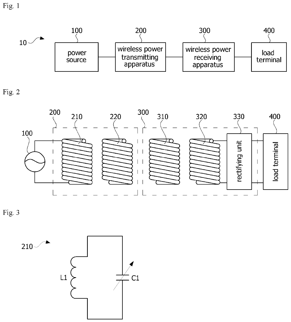
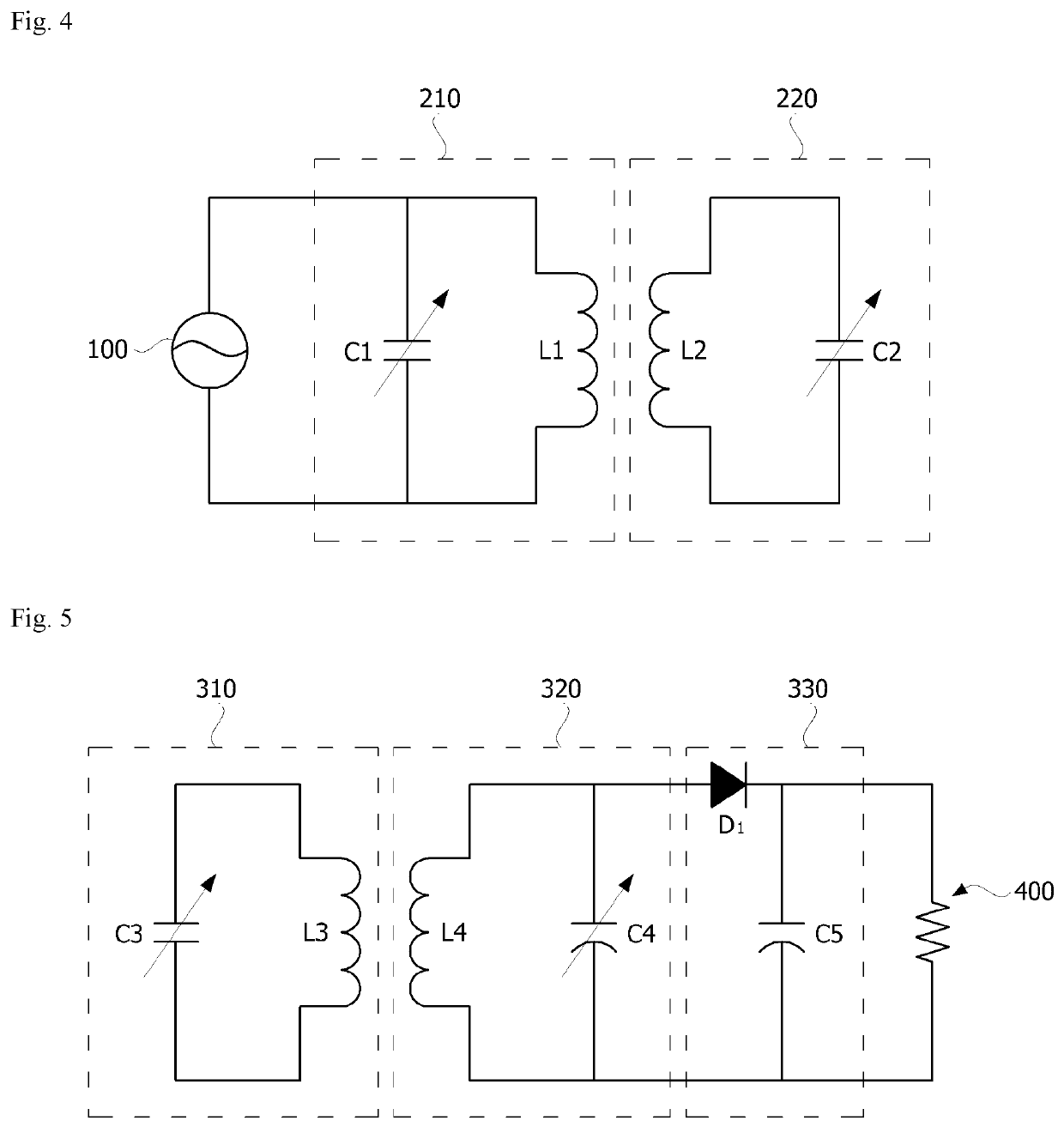
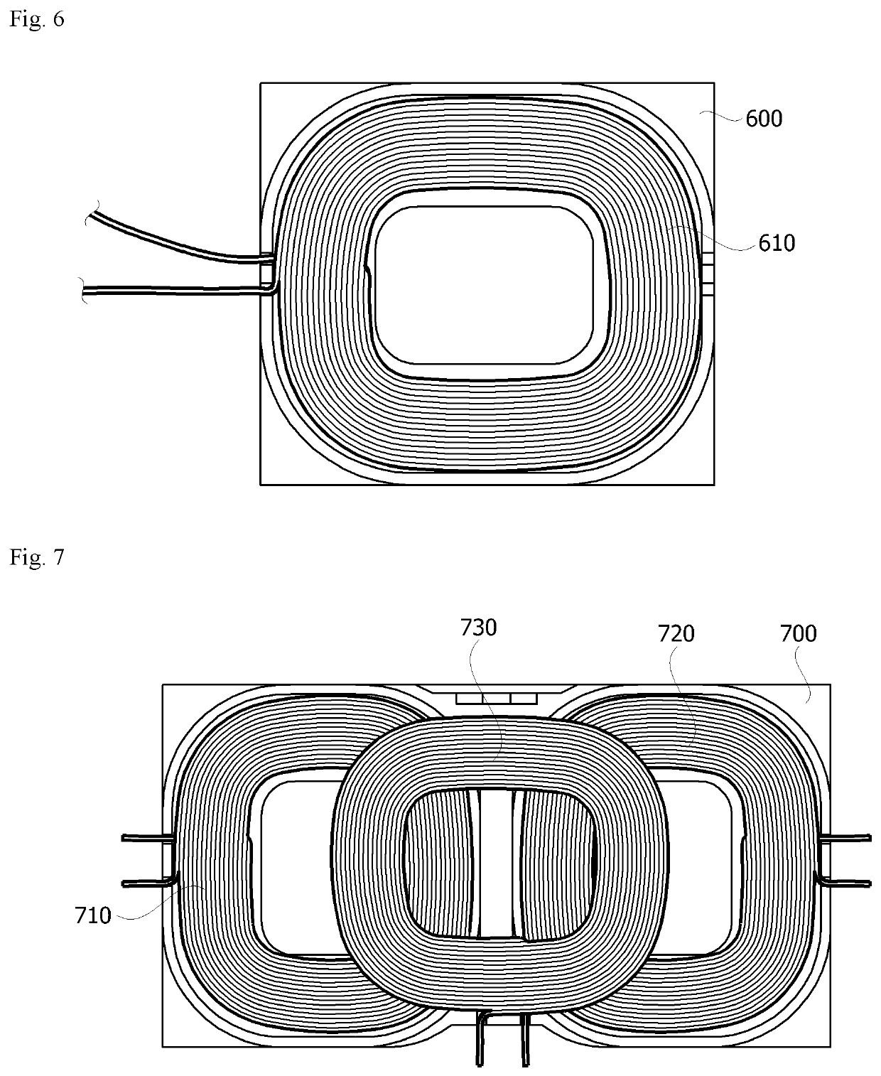
According to an aspect of the present invention, a wireless power transmitting apparatus of a wireless charging system includes a substrate, a first bonding layer formed on the substrate, a soft magnetic layer formed on the first bonding layer, a second bonding layer formed on the soft magnetic layer and a transmitting coil formed on the second bonding layer, wherein at least one of the first bonding layer and the second bonding layer includes a magnetic substance.

Description

CROSS REFERENCE TO RELATED APPLICATIONS[0001]This application is the National Phase of PCT International Application No. PCT / KR2015 / 009462, filed on Sep. 8, 2015, which claims priority under 35 U.S.C. 119(a) to Patent Application No. 10-2014-0130529, filed in the Republic of Korea on Sep. 29, 2014, all of which are hereby expressly incorporated by reference into the present application.TECHNICAL FIELD[0002]The present invention relates to wireless charging, and more specifically, a wireless power transmitting apparatus and a wireless power receiving apparatus included in a wireless charging system.BACKGROUND ART[0003]As wireless communications technology is continuing to advance, wireless power transmitting / receiving technology which wirelessly transmits power to electronic devices has started to receive more attention. This type of wireless power transmitting / receiving technology may be diversely applied not only to battery charging of mobile terminals but also to delivery of power...

Claims


Application Information

Patent Timeline
Patent Type & Authority Patents(United States)
IPC IPC(8): H02J7/02H01F1/26H01F27/28H02J50/50H01F27/36H02J50/12H01F1/147H01F1/20H01F27/245H01F27/255H01F38/14
CPCH02J7/025H01F1/14733H01F1/14775H01F1/14791H01F1/20H01F1/26H01F27/245H01F27/255H01F27/2804H01F27/2871H01F27/36H01F38/14H02J50/12H02J50/50H02J50/005H02J50/70H01F27/366
Inventor LEE, YUN BOKSONG, YOUNG KILHYUN, SOON YOUNG
Owner NERA INNOVATIONS LTD
Why Eureka
Eureka Blog
Learn More