Multi-beam laser spot welding of coated steels

a laser spot welding and coating technology, applied in welding/soldering/cutting articles, metal working devices, manufacturing tools, etc., can solve problems such as source of weld defects, achieve strong and durable weld joints, reduce the overall combined irradiance of laser beams, and improve welding efficiency.

Active Publication Date: 2021-10-19
GM GLOBAL TECH OPERATIONS LLC
View PDF76 Cites 4 Cited by
  • Summary
  • Abstract
  • Description
  • Claims
  • Application Information

AI Technical Summary

Benefits of technology

[0008]A method of laser spot welding a workpiece stack-up that includes overlapping steel workpieces is disclosed. The workpiece stack-up includes two or more steel workpieces, and at least one of those steel workpieces (and possibly all of the steel workpieces) includes a surface coating. The surface coating may be comprised of a zinc-based material or an aluminum-based material, and preferably has a thickness that lies within the range of 2 μm to 50 μm. While any of these surface coating(s) may be applied to an underlying base steel substrate for a variety of reasons—a non-limiting list of reasons being to improve corrosion protection, impart strength, and / or improve formability—their presence can be a source of weld defects in the laser spot weld joint. The disclosed laser spot welding method minimizes the impact that surface coatings may have on the laser spot weld joint without requiring but of course not prohibiting—the practice of certain more conventional procedures such as, for example, the intentional imposition of gaps between the steel workpieces at the faying interface where the surface coating is present by way of laser scoring or mechanical dimpling.
[0011]The overall combined irradiance of the laser beams may be increased from its initial level to its elevated level by reducing the total projected sectional area of the laser beams—which is the surface area provided when the individual sectional areas of the laser beams are combined—at a plane of the top surface of the workpiece stack-up. For example, in one embodiment, the focal points of the laser beams may be moved along their longitudinal beam axes relative to the top surface of the workpiece stack-up such that a more focused portion of each beam intersects the plane of the top surface. As another example, the mean angle of incidence of the plurality of laser beams may be decreased to reduce the eccentricity of the individual projected sectional areas of the laser beams (that together constitute the total projected sectional area of the laser beams) at the plane of the top surface. The overall combined irradiance of the laser beams during creation and growth of the molten steel weld pool, moreover, may be controlled to operate in either conduction welding mode or keyhole welding mode. In conduction welding mode, the energy of the laser beams is conducted as heat through the steel workpieces to create only the molten steel weld pool. In keyhole welding mode, the laser beams vaporize the steel workpieces and produce a keyhole or keyholes in the immediate vicinity of the laser beams within the molten steel weld pool.
[0012]After the molten steel weld pool has penetrated into the workpiece stack-up far enough to intersect the faying interface(s), the transmission of the laser beams is ceased at the weld site. This may be done without first changing the current status of the total projected sectional area of the laser beams or, in other instances, it may be done after increasing the total projected sectional area of the laser beams at a plane of the top surface of the workpiece stack-up so as to decrease the overall combined irradiance of the laser beams. Upon ceasing transmission of the laser beams, the keyhole (if present) collapses and the molten steel weld pool cools and solidifies into a laser spot weld joint comprised of resolidified composite steel workpiece material derived from each of the steel workpieces penetrated by the molten steel weld pool. The resolidified composite steel workpiece material autogenously fusion welds the overlapping steel workpieces together at the weld site. And, unlike conventional laser spot welding practices, the laser spot weld joint formed according to the disclosed method includes provisions related to the mechanics of the laser beams that help keep the surface coatings of the one or more steel workpieces from negatively affecting the strength and other mechanical properties of the laser spot weld joint to an unsatisfactory extent. The ability to inhibit the surface coatings from contributing to the formation of weld defects within the laser spot weld joint ultimately leads to strong and durable weld joints that can be consistently attained.

Problems solved by technology

While any of these surface coating(s) may be applied to an underlying base steel substrate for a variety of reasons—a non-limiting list of reasons being to improve corrosion protection, impart strength, and / or improve formability—their presence can be a source of weld defects in the laser spot weld joint.

Method used


Image

  • Multi-beam laser spot welding of coated steels
  • Multi-beam laser spot welding of coated steels
  • Multi-beam laser spot welding of coated steels

Examples


Embodiment Construction

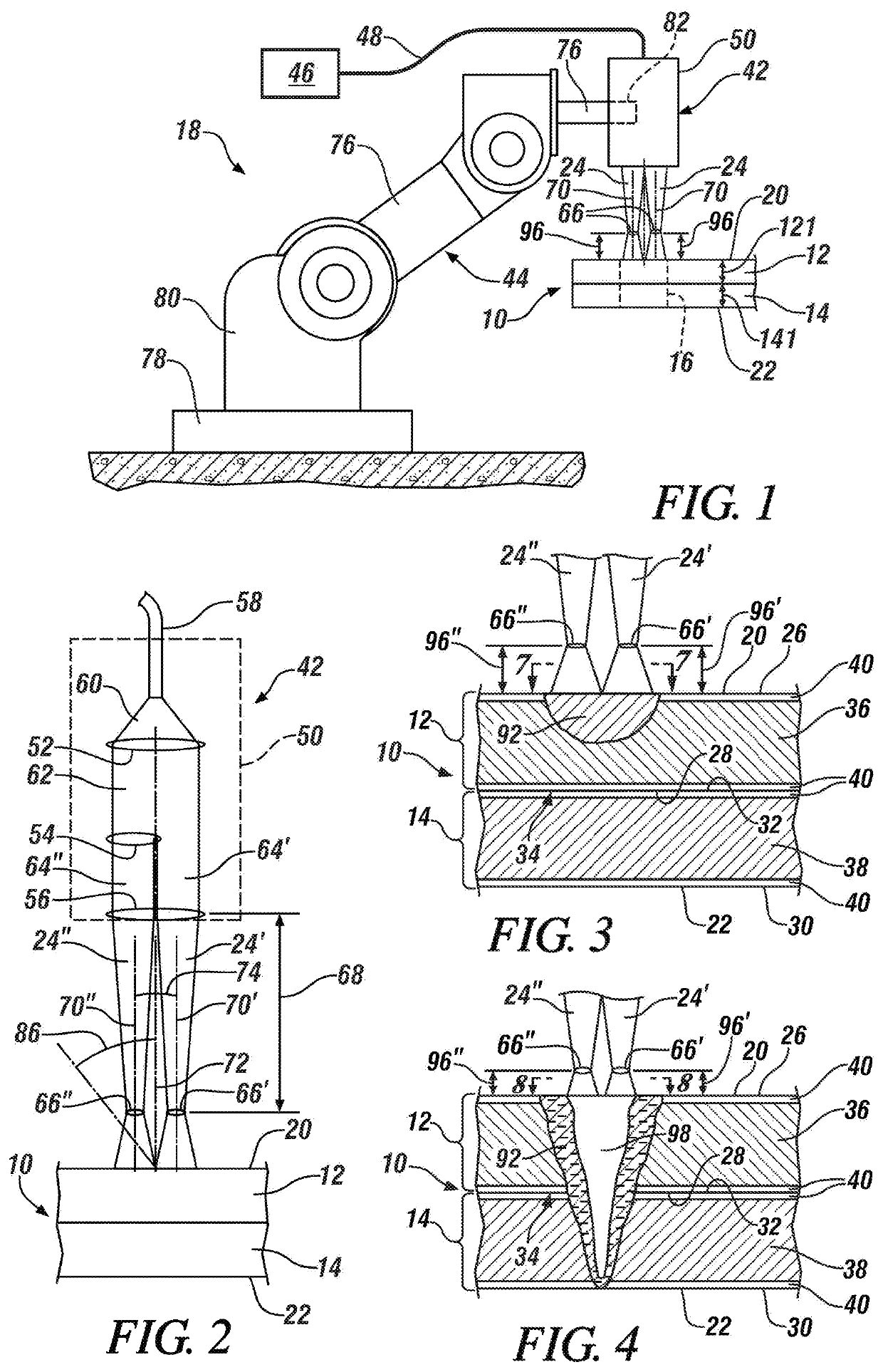
[0029]The disclosed method of laser spot welding a workpiece stack-up comprised of two or more overlapping steel workpieces calls for increasing an overall combined irradiance of a plurality of laser beams trained at a top surface of the stack-up at a weld site during growth of a created molten steel weld pool. Any type of conventional laser welding apparatus may be employed to direct the multiple laser beams towards the top surface of the workpiece stack-up and to increase the overall combined irradiance of the laser beams. Moreover, the overall combined irradiance range of the multiple laser beams may be controlled to perform the method in either conduction welding mode or keyhole welding mode. The laser beams may thus be solid-state laser beams or gas laser beams depending on the characteristics of the steel workpieces being joined and the laser welding mode desired to be practiced. Some notable solid-state lasers that may be used are a fiber laser, a disk laser, a diode laser, a...


PUM

PropertyMeasurementUnit
distanceaaaaaaaaaa
mean angle of incidenceaaaaaaaaaa

Abstract

A method of laser spot welding a workpiece stack-up (10) that includes at least two overlapping steel workpieces (12, 14, 150) is disclosed. The method includes directing a plurality of laser beams (24, 24′, 24″) at the top surface (20) of the workpiece stack-up to create a molten steel weld pool (92) that penetrates into the stack-up. The molten steel weld pool is then grown to penetrate further into the stack-up by increasing an overall combined irradiance of the laser beams while reducing the total projected sectional area (88) of the laser beams at a plane of the top surface of the workpiece stack-up. Increasing the overall combined irradiance of the laser beams may be accomplished by moving the focal points (66, 66′, 66″) of the laser beams closer to the top surface or by reducing the mean angle of incidence (86) of the laser beams so as to reduce the eccentricity of the individual projected sectional areas of the laser beams.

Description

TECHNICAL FIELD[0001]The technical field of this disclosure relates generally to laser welding and, more particularly, to a method of laser spot welding together two or more overlapping steel workpieces with multiple laser beams.BACKGROUND[0002]Laser spot welding is a metal joining process in which, conventionally, a single laser beam is directed at a metal workpiece stack-up to provide a concentrated energy source capable of effectuating a weld joint between the overlapping constituent metal workpieces. In general, two or more metal workpieces are first aligned and stacked relative to one another such that their faying surfaces overlap and confront to establish a faying interface (or faying interfaces) that extends through an intended weld site. A laser beam is then directed towards and impinges a top surface of the workpiece stack-up. The heat generated from the absorption of energy from the laser beam initiates melting of the metal workpieces and creates a molten metal weld pool ...

Claims


Application Information

Patent Timeline
Patent Type & Authority Patents(United States)
IPC IPC(8): B23K26/322B23K26/067B23K26/22B23K26/244B23K101/34
CPCB23K26/322B23K26/0676B23K26/22B23K26/244B23K2101/35
Inventor YANG, DAVIDTAO, WU
Owner GM GLOBAL TECH OPERATIONS LLC
Why Eureka
Try Eureka