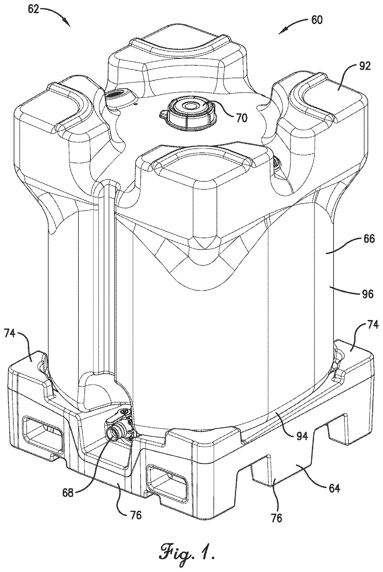
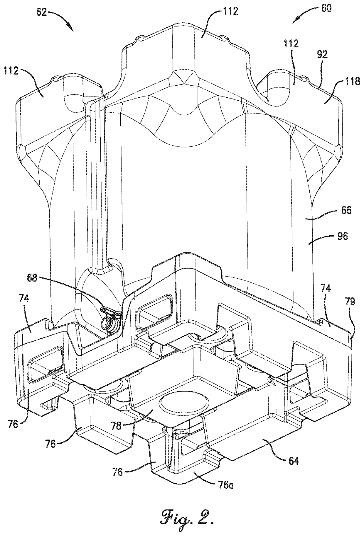
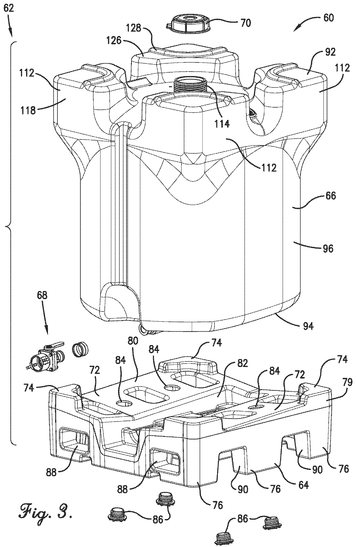
Bulk container with bottom configured for drainage

Active Publication Date: 2021-10-19
CUSTOM METALCRAFT
View PDF21 Cites 0 Cited by
  • Summary
  • Abstract
  • Description
  • Claims
  • Application Information

AI Technical Summary

Benefits of technology

The present invention provides a container that can better handle bulk materials. The container has a receptacle with a bottom and side that work together to form a chamber. There is also a drain opening that allows materials to flow out of the chamber. The bottom has two floor sections that work together to push materials towards the drain opening. Overall, this design provides better access to the chamber and allows for easier handling of bulk materials.

Problems solved by technology

However, conventional intermediate bulk containers have several deficiencies.
For instance, known bulk containers drain poorly and generally have low spots that restrict liquid and / or solid materials contained therein from being drained completely.
Prior art containers designed for stacking commonly have structural weaknesses that unduly limit stacking loads and / or limit container storage capacity.
Conventional bulk containers also have container lids that are time-consuming to install or remove.
It is also known for lids of such containers to be inadvertently displaced from the receptacle under extreme conditions (e.g., when the container is over-pressurized).

Method used


Image

  • Bulk container with bottom configured for drainage
  • Bulk container with bottom configured for drainage
  • Bulk container with bottom configured for drainage

Examples


second embodiment

[0077]Initially turning to FIGS. 32-36, an alternative container 200 is constructed in accordance with the present invention. The depicted container 200 preferably includes a pallet 202, an alternative receptacle 204, valve assembly 206, and an alternative lid 208.

[0078]In the illustrated embodiment, the receptacle 204 preferably includes an alternative receptacle top 210, a receptacle bottom 212, and a receptacle side 214 (see FIG. 32). The receptacle top 210 is configured to at least partly support another receptacle 204 stacked relative thereto. The receptacle top 210 preferably includes alternative pillars 216 and an alternative fill neck 218.

[0079]The fill neck 218 is configured to receive the lid 208 and includes a tube 220 that presents a fill opening 222 (see FIGS. 33 and 34). The depicted lid 208 preferably comprises a conventional, large-mouth lid for an intermediate bulk container. The lid 208 is operable to be removably secured to the fill neck 218 with an adjustable ban...

third embodiment

[0083]Turning to FIGS. 37-43, an alternative container 300 is constructed in accordance with the present invention. The depicted container 300 preferably includes a pallet 302, an alternative receptacle 304, valve assembly 306, and an alternative removable lid 308. The container 300 also preferably presents a container chamber 309. As will be explained, the receptacle 304 and lid 308 are particularly configured to receive bulk material and to experience a pressure differential for which an internal container pressure is greater than ambient pressure.

[0084]In the illustrated embodiment, the receptacle 304 preferably includes an alternative receptacle top 310, a receptacle bottom 312, and a receptacle side 314 (see FIG. 37). The receptacle top 310 is configured to at least partly support another receptacle 304 stacked relative thereto. The receptacle top 310 preferably includes pillars 316 and an alternative fill neck 318.

[0085]The fill neck 318 is configured to removably receive the ...

fourth embodiment

[0092]Turning to FIGS. 44-50, an alternative container 400 is constructed in accordance with the present invention. The depicted container 400 preferably includes a pallet (not shown), an alternative receptacle 404, valve assembly (not shown), and an alternative removable lid 408. The container 400 also preferably presents a container chamber 409. As will be explained, the receptacle 404 and lid 408 are particularly configured to receive bulk material and to experience a pressure differential for which an internal container pressure is greater than ambient pressure.

[0093]In the illustrated embodiment, the receptacle 404 preferably includes an alternative receptacle top 410, a receptacle bottom (not shown), and a receptacle side 414 (see FIG. 44). The receptacle top 410 preferably includes pillars 416 and an alternative fill neck 418.

[0094]The fill neck 418 is configured to removably receive the lid 408. The fill neck 418 includes a receptacle connector 420 to engage the lid 408 and ...


PUM


Abstract

A container includes a receptacle including an upright receptacle side and a receptacle bottom that cooperate to at least partly define a container chamber. The bottom presents a peripheral margin, with the side being attached to the bottom along the peripheral margin and extending upwardly relative to the bottom along an upright container axis. The receptacle further includes a drain configured to permit material flow out of the chamber, with the drain intersecting the bottom to define a drain opening that fluidly communicates with the chamber. The drain opening is spaced inboard from the peripheral margin and is laterally offset from the container axis in an offset direction. The bottom includes first and second floor sections extending inboard from the peripheral margin and joined relative to each other along a first gutter area adjacent the drain opening. The first floor section slopes downwardly toward the first gutter area in the offset direction and the second floor section slopes downwardly toward the first gutter area in a direction opposite the offset direction, with the floor sections configured to cooperatively advance material within the chamber toward the drain opening.

Description

CROSS-REFERENCE TO RELATED APPLICATIONS[0001]This application is being filed contemporaneously with U.S. Utility application Ser. No. 16 / 810,330, entitled STACKABLE BULK CONTAINER, and U.S. Utility application Ser. No. 16 / 810,361, entitled BULK CONTAINER WITH QUICK-COUPLE LID, U.S. Design application Ser. No. 29 / 726,799, entitled CONTAINER AND PALLET, U.S. Design application Ser. No. 29 / 726,803, entitled CONTAINER, and U.S. Design application Ser. No. 29 / 726,808, entitled CONTAINER, each of which is hereby incorporated in its entirety by reference herein.BACKGROUND1. Field[0002]The present invention relates generally to containers. More specifically, embodiments of the present invention concern a container configured to receive bulk material therein and to permit efficient material drainage from the container.2. Discussion of Prior Art[0003]Intermediate bulk containers are well known in the art for their use in shipping bulk quantities of liquid and solid materials. Conventional con...

Claims


Application Information

Patent Timeline
IPC IPC(8): B65D88/02B65D88/54B65D21/02B65D19/00
CPCB65D88/022B65D19/003B65D21/0209B65D88/02B65D88/54B65D2588/125B65D1/14B65D19/18B65D2519/00034B65D2519/00069B65D2519/00174B65D2519/00318B65D2519/00338B65D2519/00497B65D2519/00507B65D2519/00621B65D2519/00641B65D2519/00975B65D2519/00805B65D21/0224B65D2519/00422B65D2519/00268B65D2519/00288B65D1/20B67D7/0288
Inventor HOLDEN, CLARK AUSTINHOLDEN, DEBORAH NICHOLEMEASE, RODNEY ARTHURBRUNN, PETER JOSEPHSTOUT, GREGORY PAULHOLDEN, DWAYNE
Owner CUSTOM METALCRAFT
Why Eureka
Try Eureka