
Tubular membrane with spiral flow

a technology of tubular membrane and spiral flow, which is applied in the direction of membranes, water contaminants, water/sludge/sewage treatment, etc., can solve the problems of common clogging, reduce fouling and clogging of membranes, and increase the energy efficiency of membrane tubes.

Active Publication Date: 2021-10-26
SWIRLTEX HLDG CORP
View PDF11 Cites 0 Cited by
  • Summary
  • Abstract
  • Description
  • Claims
  • Application Information

AI Technical Summary

Benefits of technology

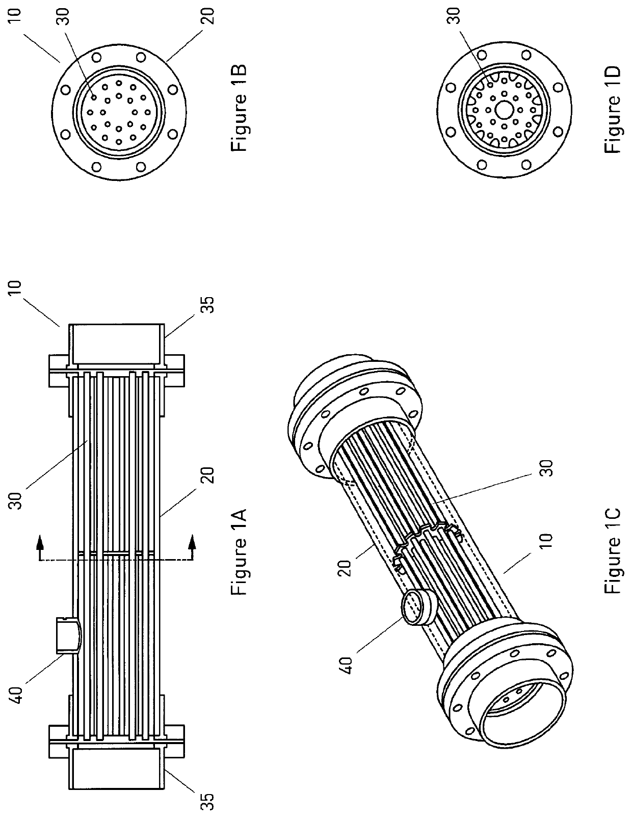
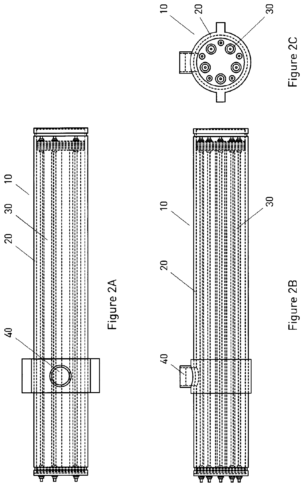
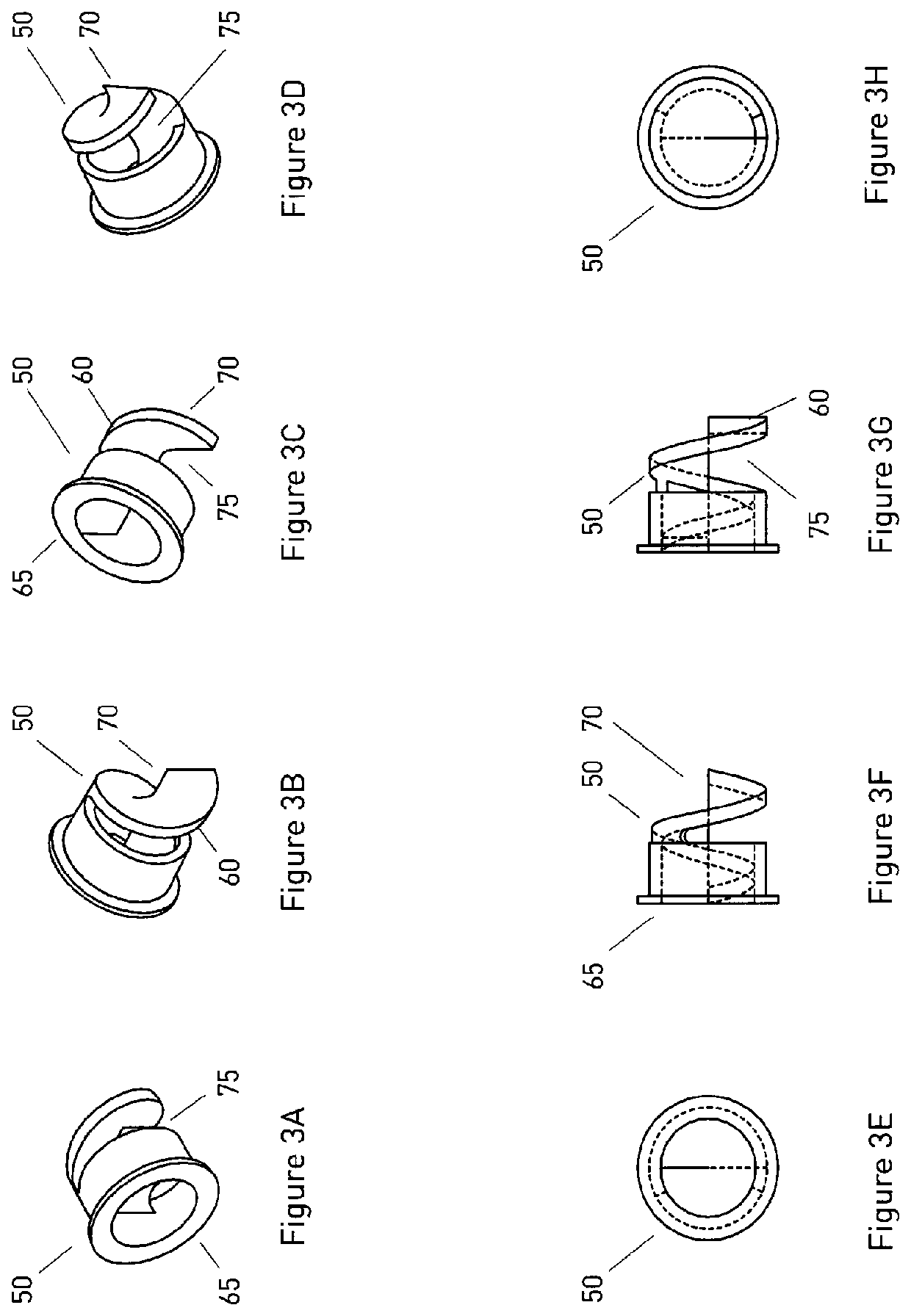
The patent describes a new membrane tube design that increases efficiency in separating liquids and gases. The design creates a vortex of the fluid, which causes a centrifugal force that pulls the denser fluid toward the inner surface of the membrane tube, while the less dense fluid flows to the center. This separation process reduces the effects of oil on the membrane, which extends its life. The design can be used in various applications such as oil / water separation, waste water treatment, pharmaceutical and frack water treatment, and desalination. The system provides a more efficient separation process and higher filtration efficiencies.

Problems solved by technology

This clogging is a common problem with available membranes.

Method used


Image

  • Tubular membrane with spiral flow
  • Tubular membrane with spiral flow
  • Tubular membrane with spiral flow

Examples


Embodiment Construction

[0029]A detailed description of one or more embodiments of the invention is provided below along with accompanying figures that illustrate the principles of the invention. The invention is described in connection with such embodiments, but the invention is not limited to any embodiment. The scope of the invention is limited only by the claims and the invention encompasses numerous alternatives, modifications and equivalents. Numerous specific details are set forth in the following description in order to provide a thorough understanding of the invention. These details are provided for the purpose of example and the invention may be practiced according to the claims without some or all of these specific details. For the purpose of clarity, technical material that is known in the technical fields related to the invention has not been described in detail so that the invention is not unnecessarily obscured.

[0030]The term “invention” and the like mean “the one or more inventions disclose...


PUM

PropertyMeasurementUnit
densityaaaaaaaaaa
sizeaaaaaaaaaa
concentrationaaaaaaaaaa

Abstract

A permeable membrane tube to separate mixed fluids is provided, including a cyclone generator configured to cause fluid entering the permeable tube to flow in a spiral direction. The cyclonic generator may be a plug positioned at the fluid entrance of the membrane tube. The fluid passes through the permeable membrane tube, which has a center axis along a length of the tube, and flows in the spiral direction thereby separating the fluid into first and second portions, wherein the first portion comprises fluid having a greater density than the second portion and the first portion is directed to an inner surface of the tube.

Description

RELATED APPLICATIONS[0001]This application claims the benefit of U.S. Provisional Patent Application No. 62 / 111,498, filed Feb. 3, 2015, which is hereby incorporated by reference in its entirety.FIELD OF THE INVENTION[0002]This invention relates to membrane filtration systems, and more particularly to increasing the efficiency of the membrane and separation of a liquid stream passing through the membrane.BACKGROUND OF THE INVENTION[0003]Membrane filtration operates on the principle that when a liquid is passed across or through a physical barrier, particles whose size is larger than the pores in the membrane are retained on one side of the barrier, while the remaining liquid passes through. This principle holds true for coarse filters, such as metal sieves, as well as much finer materials which are capable of selective filtration and concentration of molecules of different sizes. Membrane filtration often uses a polymer or similar material with an extremely small pore size and may b...

Claims


Application Information

Patent Timeline
Patent Type & Authority Patents(United States)
IPC IPC(8): C02F1/24C02F1/40C02F101/32B01D63/06B01D63/02B01D17/02B01D69/04C02F1/44
CPCB01D63/06B01D17/0205B01D63/02B01D69/04C02F1/24C02F1/40C02F1/44B01D2313/086B01D2313/105C02F2101/32
Inventor CHRISTOU, PETER JAMES
Owner SWIRLTEX HLDG CORP
Learn More