
Water treatment apparatus with circulating flow path and water treatment method using the same

a technology of water treatment apparatus and flow path, which is applied in the direction of multi-stage water/sewage treatment, water treatment parameter control, membranes, etc., can solve the problems of increasing cost, affecting and the recovery rate of the membrane filtering device may not be satisfactory in certain situations, so as to enhance the filtering efficiency of the membrane filtering device without increasing the usage amount of cohesive agents

Active Publication Date: 2014-01-23
LG CHEM LTD
View PDF6 Cites 0 Cited by
  • Summary
  • Abstract
  • Description
  • Claims
  • Application Information

AI Technical Summary

Benefits of technology

The present invention provides a water treatment apparatus and method that can enhance the filtering efficiency of a membrane filtering device without increasing the usage amount of a cohesive agent. The invention controls the growth of flocs in a lower stream side of a pump, preventing degradation of filtering efficiency and a degree of contamination of treatment water. By eliminating the need for a flocculator or settling tank, the invention reduces installation restrictions and construction costs.

Problems solved by technology

In the water treatment method as described above, a degree of clumping of foreign materials in raw water significantly affects filtering efficiency of the membrane filtering device.
However, although flocs are grown sufficiently in the flocculator or a settling tank, a recovery rate in the membrane filtering device may not be satisfactory in certain situations.
In order to solve this problem, a method of increasing a usage amount of cohesive agent may be considered; however, this leads to an increase in cost.
In addition, since additional facilities such as a mixing tank, a flocculator, or a settling tank are required, an installation place is restricted and cost for construction is increased.

Method used


Image

  • Water treatment apparatus with circulating flow path and water treatment method using the same
  • Water treatment apparatus with circulating flow path and water treatment method using the same
  • Water treatment apparatus with circulating flow path and water treatment method using the same

Examples


Embodiment Construction

[0023]Hereinafter, a water treatment apparatus according to exemplary embodiments of the present invention will be described in detail with reference to the accompanying drawings.

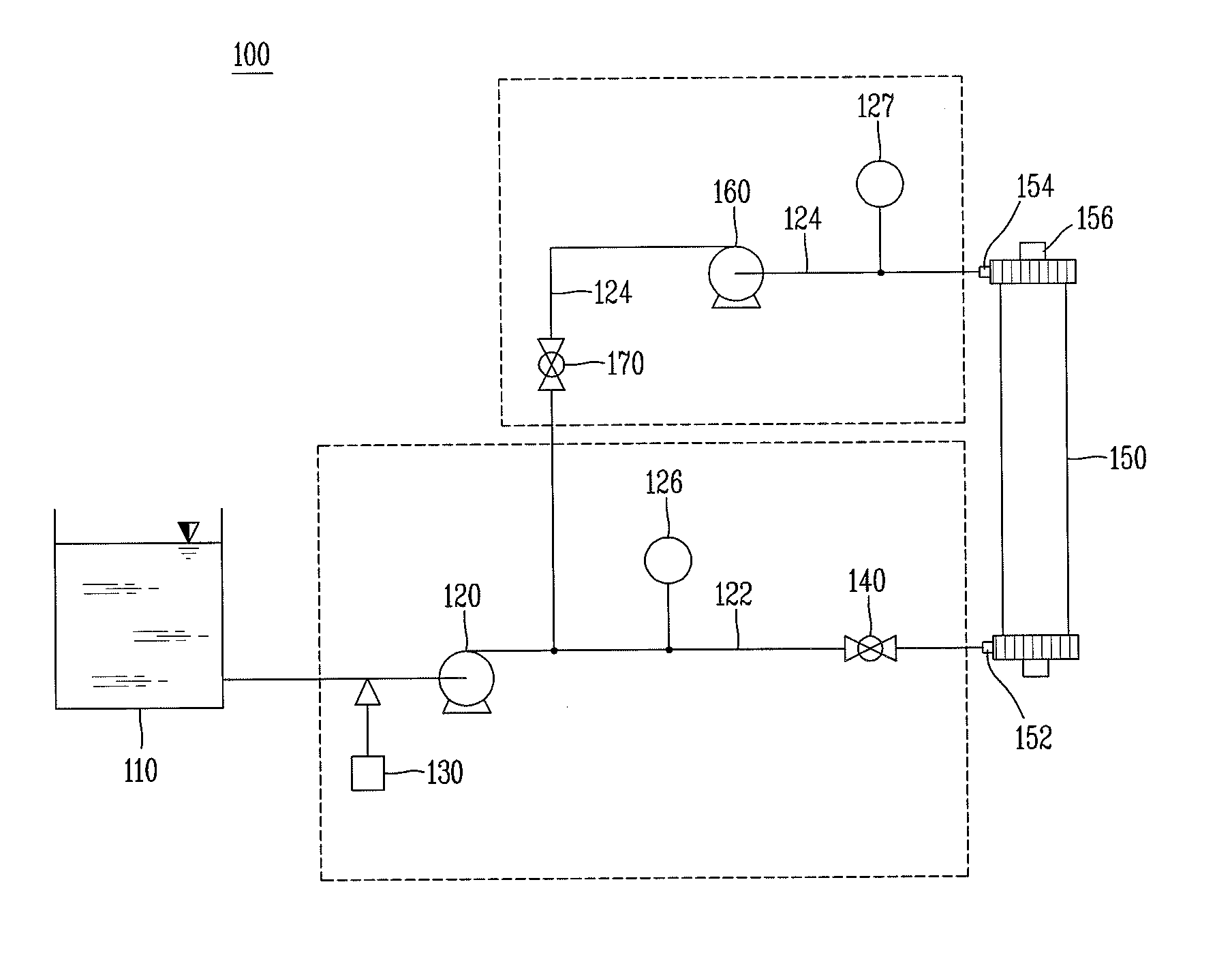
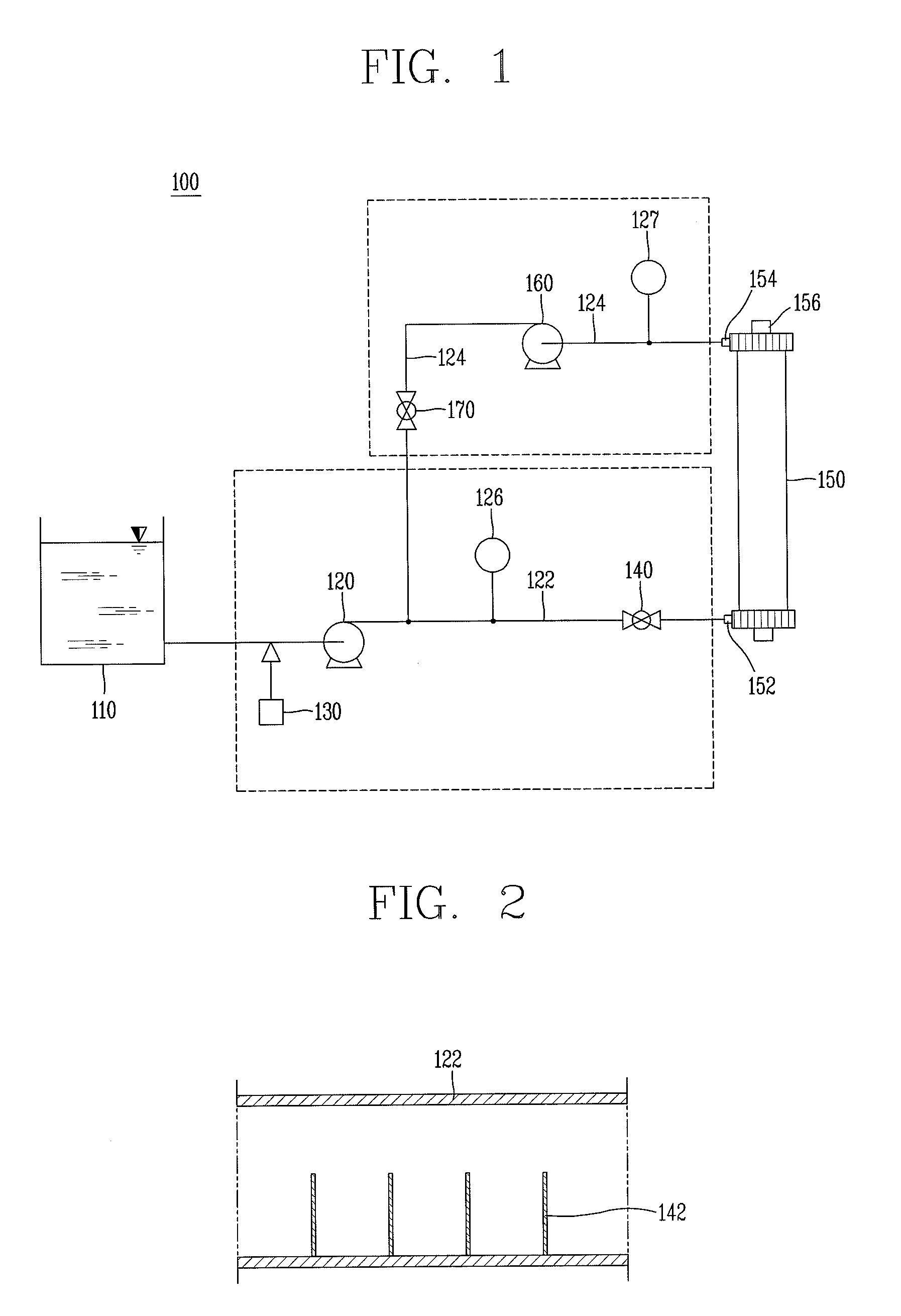
[0024]FIG. 1 is a view schematically illustrating a water treatment apparatus according to a first exemplary embodiment of the present invention. Referring to FIG. 1, the water treatment apparatus 100 according to a first exemplary embodiment of the present invention includes a raw water tank 110 temporarily storing raw water as a treatment target, and raw water stored in the raw water tank 110 is introduced to a raw water pump 120.

[0025]Meanwhile, a cohesive agent input device 130 is positioned in an upper stream side of the raw water pump 120. Thus, in a state in which a cohesive agent is input (or applied) to raw water, the raw water is introduced to the raw water pump 120. The cohesive agent input to the raw water is pressurized within the raw water pump 120 and discharged to the outside, and in this pr...


PUM

PropertyMeasurementUnit
flow rateaaaaaaaaaa
slanting angleaaaaaaaaaa
timeaaaaaaaaaa

Abstract

A water treatment apparatus and a water treatment method using the same are provided. The water treatment apparatus includes a cohesive agent input device configured to input a cohesive agent to raw water, a membrane filtering device, a raw water pump configured to transfer raw water including the cohesive agent therein to the membrane filtering device, a water supply flow path connecting a discharge side of the raw water pump to the inlet of the membrane filtering device, a circulation flow path connecting the raw water discharge opening of the membrane filtering device to the water supply flow path and a circulation pump provided in the circulation flow path to transfer discharged raw water to the water supply flow path.

Description

CROSS-REFERENCE TO RELATED APPLICATION[0001]Pursuant to 35 U.S.C. §119(a), this application claims the benefit of earlier filing date and right of priority to Korean Application No. 10-2012-0077928, filed on Jul. 17, 2012, the contents of which is incorporated by reference herein in its entirety.BACKGROUND OF THE INVENTION[0002]1. Field of the Invention[0003]The present disclosure relates to a water treatment apparatus and a water treatment method using the same, and particularly, to a water treatment apparatus and method for clumping foreign materials included in raw water.[0004]2. Description of Related Art[0005]In general, a physical, chemical water treatment method includes a clumping-precipitating-filtering process, a clumping-floating-filtering process, or the like, and here, the clumping process is a process of growing fine colloid particles floating in raw water to flocs, a grain having a size sufficient for precipitation and filtering. In the clumping process, a cohesive ag...

Claims


Application Information

Patent Timeline
Patent Type & Authority Applications(United States)
IPC IPC(8): C02F1/44
CPCC02F1/44B01D61/16B01D61/22C02F1/444C02F1/5209C02F1/5281B01D2311/04B01D2311/2642C02F2209/001C02F2209/11C02F2209/40C02F2301/02C02F2301/046B01D61/145B01D61/147B01D2311/2523B01D2311/246B01D2311/16C02F1/52B01D61/00
Inventor PARK, RAYOUNGYI, YONGJOOCHOI, WOONG
Owner LG CHEM LTD
Learn More