Test apparatus

a test apparatus and test tube technology, applied in the field of test tubes, can solve the problems of narrowing the field of view of the operator, reducing components (such as the indenter) of the test tube, and difficult to test the strength of specimens, so as to reduce the visibility, narrow the field of view, and reduce the visibility of specimens.

Active Publication Date: 2021-11-02
DISCO CORP
View PDF6 Cites 0 Cited by
  • Summary
  • Abstract
  • Description
  • Claims
  • Application Information

AI Technical Summary

Benefits of technology

[0006]When the test apparatus measures the strength of the specimen, the test apparatus presses the indenter against the specimen until the specimen is broken and detects the maximum value of the load applied to the indenter, for example. When the specimen is broken, fragments of the specimen are scattered. Therefore, the operator who operates the test apparatus wears a protector such as goggles during the test. However, wearing the protector narrows the field of view of the operator and reduces the visibility of the specimen and the components (such as the indenter) of the test apparatus. The reduced visibility makes it difficult to test the strength of the specimen.
[0007]The present invention has been made in view of the above-described issue. It is an object of the present invention to provide a test apparatus capable of facilitating a strength test of a specimen.
[0010]In the test apparatus according to the described aspect of the present invention, when the specimen supported by the support unit is pressed by the indenter, the upper container is positioned so as to cover the specimen. Therefore, the upper container positioned in this manner prevents fragments of the specimen from scattering outside the test apparatus when the specimen is pressed and broken by the indenter. As described above, since the upper container prevents the fragments of the specimen from scattering outside the test apparatus, the operator of the test apparatus does not need to wear a protector such as goggles when testing the strength of the specimen. This, in turn, prevents a reduction in visibility of the specimen and the components (such as the indenter) of the test apparatus due to wearing of the protector, and facilitates the strength test of the specimen.

Problems solved by technology

However, wearing the protector narrows the field of view of the operator and reduces the visibility of the specimen and the components (such as the indenter) of the test apparatus.
The reduced visibility makes it difficult to test the strength of the specimen.

Method used


Image

  • Test apparatus
  • Test apparatus
  • Test apparatus

Examples


Embodiment Construction

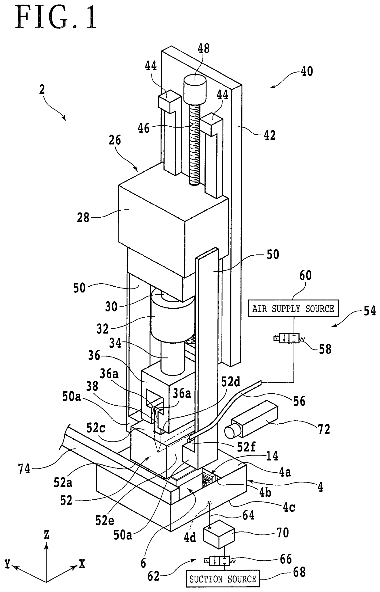
[0018]An embodiment according to an aspect of the present invention will be described below with reference to the accompanying drawings. First, an example of a configuration of a test apparatus according to the present embodiment will be described. FIG. 1 is a perspective view of a test apparatus 2 for testing the strength of a specimen (test piece).

[0019]The test apparatus 2 measures the bending strength (flexural strength) of the specimen such as a device chip. A silicon wafer has regions that are each defined by a plurality of division planned lines (streets) intersecting each other. Each region includes a device such as an IC or LSI. Dividing the silicon wafer along the plurality of division planned lines produces device chips, for example.

[0020]There is no limitation to, for example, the type, the material, the shape, the structure, and the size of the specimen whose strength is measured by the test apparatus 2. For example, the specimen may be a test chip obtained by dividing ...


PUM

PropertyMeasurementUnit
strengthaaaaaaaaaa
bending strengthaaaaaaaaaa
strength testaaaaaaaaaa

Abstract

A test apparatus for measuring strength of a specimen includes: a lower container having an opening that opens upward; an upper container having an opening that opens downward and being sized to be insertable into the opening of the lower container; a support unit that is provided in the opening of the lower container and supports the specimen; a pressing unit including an indenter that presses the specimen, and a load measurement unit that measures a load applied to the indenter; and a movement mechanism that moves the indenter closer and away relative to the support unit, in which when the specimen supported by the support unit is pressed by the indenter moved by the movement mechanism, the upper container is positioned so as to cover the specimen.

Description

BACKGROUND OF THE INVENTIONField of the Invention[0001]The present invention relates to a test apparatus for measuring the strength of a specimen.Description of the Related Art[0002]A plurality of devices such as an integrated circuit (IC) or large-scale integration (LSI) is formed on a semiconductor wafer. Dividing the semiconductor wafer produces a plurality of device chips each including one of these devices. The device chips are built in various electronic equipment typified by mobile phones and personal computers.[0003]A cutting apparatus is used to divide a semiconductor wafer. The cutting apparatus includes a chuck table and a cutting unit, for example. The chuck table holds the semiconductor wafer. The cutting unit includes an annular cutting blade mounted thereon. The cutting blade is used to cut the semiconductor wafer. By rotating the cutting blade and causing the cutting blade to cut into the semiconductor wafer, the semiconductor wafer is cut and divided into a pluralit...

Claims


Application Information

Patent Timeline
Patent Type & Authority Patents(United States)
IPC IPC(8): G01N3/20G01N3/08
CPCG01N3/08G01N3/20G01N2203/0282G01N2203/04G01N2203/0423G01N2203/0676G01N3/02G01N2203/0019G01N2203/0067G01N3/40G01N2203/0016G01N2203/0087
Inventor SAITO, YOSHINOBU
Owner DISCO CORP
Why Eureka
Try Eureka