
Network neighborhoods for establishing communication relationships between communication interfaces in an administrative domain

a network neighborhood and communication interface technology, applied in the field of computer networks, can solve the problems of cumbersome and time-consuming process of configuring peer relationships between routers and their interfaces, and the problem becomes more pronounced

Active Publication Date: 2021-11-02
128 TECH
View PDF138 Cites 37 Cited by
  • Summary
  • Abstract
  • Description
  • Claims
  • Application Information

AI Technical Summary

Benefits of technology

This patent describes a method and apparatus for forming a network topology in a Layer 3 network with a plurality of nodes that have interfaces. The method involves defining a plurality of neighborhoods and assigning at least one interface of each node to at least one of the neighborhoods and a communication role that is effective relative to one of the plurality of neighborhoods. The communication roles may vary, such as mesh, hub, or spoke role. The apparatus includes a grouper for defining the neighborhoods and a pair of assigners for assigning interfaces to the neighborhoods and roles. The method and apparatus allow for communication between interfaces of the plurality of nodes based on the neighborhoods and roles.

Problems solved by technology

Configuring peer relationships between routers and their interfaces can be a cumbersome and time consuming process—particularly when hundreds or thousands of routers are peered with a single router within a single administrative authority.
The problem becomes more pronounced, however, upon failure or replacement of single router (a hub router) peering with a plurality of other routers (spoke routers).

Method used


Image

  • Network neighborhoods for establishing communication relationships between communication interfaces in an administrative domain
  • Network neighborhoods for establishing communication relationships between communication interfaces in an administrative domain
  • Network neighborhoods for establishing communication relationships between communication interfaces in an administrative domain

Examples


Embodiment Construction

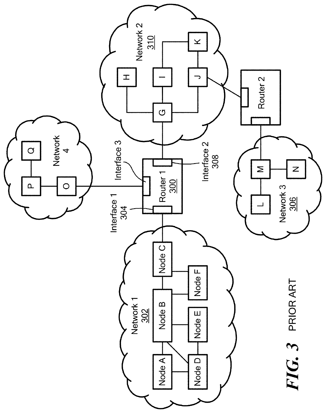
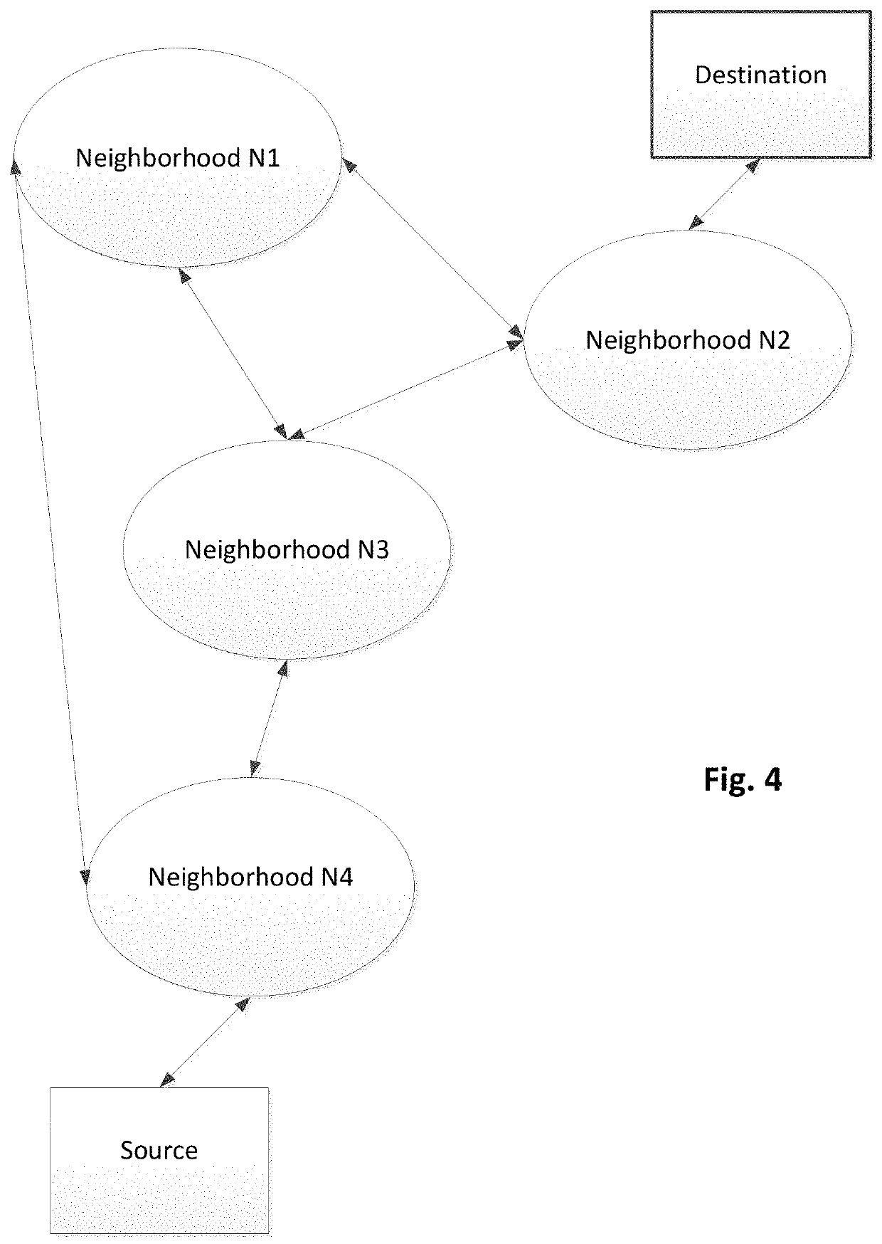
[0005]In accordance with one embodiment of the invention, a method forms and / or defines a network topology in a Layer 3 network with a plurality of nodes, where each node has at least one interface. To that end, the method defines a plurality of neighborhoods, and assigns at least one interface of each node to at least one of the neighborhoods. The method also assigns a communication role to each interface so that each communication role is effective relative to one of the plurality of neighborhoods. The method then enables communication between the interfaces of the plurality of nodes as a function of the neighborhoods and the communication roles.

[0006]A single interface may be assigned to one or more neighborhoods. For example, the act of assigning at least one interface may include assigning a given interface (of a given node) to both a first neighborhood and a second neighborhood of the plurality of neighborhoods. In addition, the act of assigning a communication role may includ...


PUM


Abstract

A method and apparatus form and / or define a network topology in a Layer 3 network with a plurality of nodes, where each node has at least one interface. To that end, the method defines a plurality of neighborhoods, and assigns at least one interface of each node to at least one of the neighborhoods. The method also assigns a communication role to each interface so that each communication role is effective relative to one of the plurality of neighborhoods. The method then enables communication between the interfaces of the plurality of nodes as a function of the neighborhoods and the communication roles.

Description

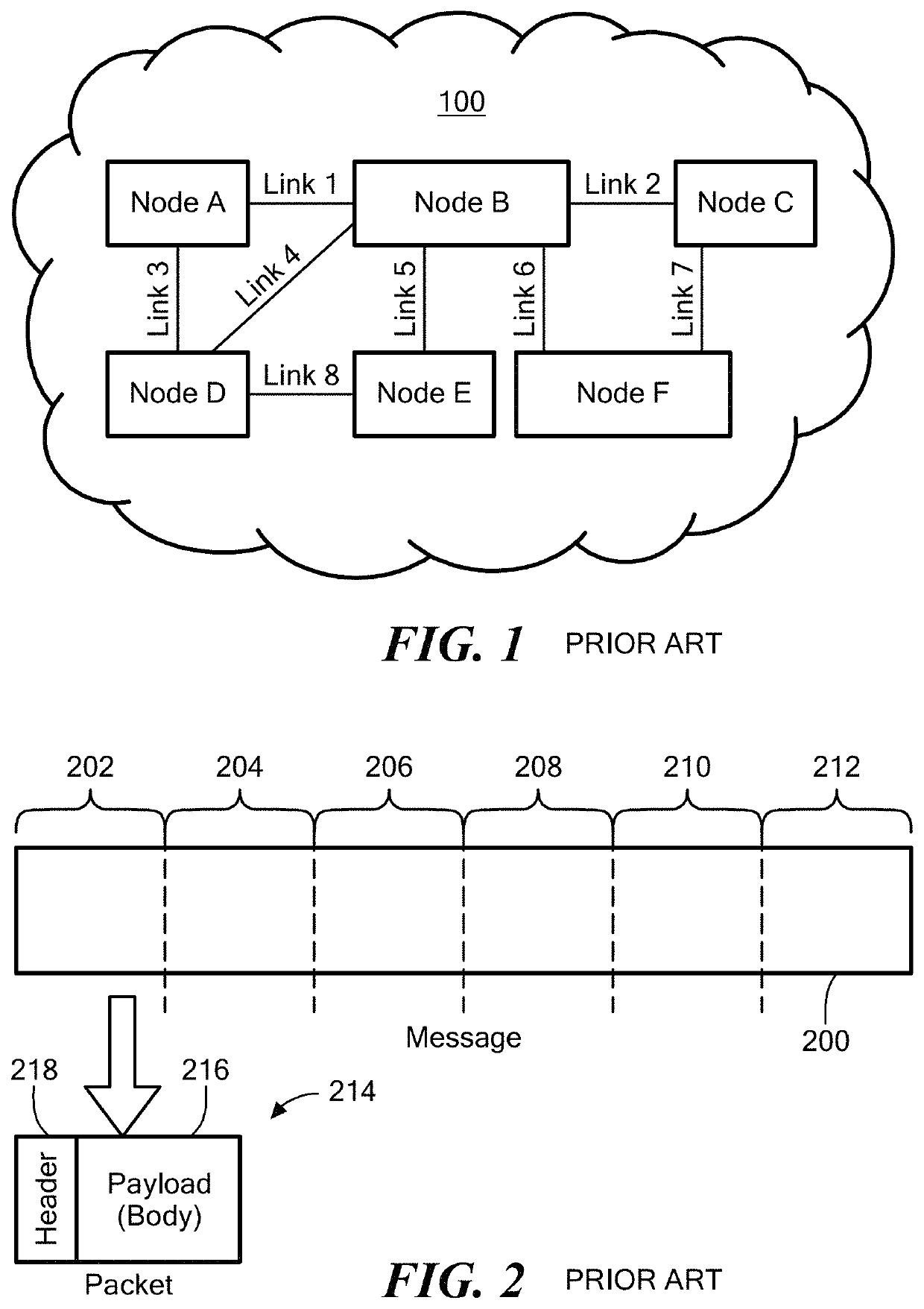
PRIORITY[0001]This patent application claims priority from provisional U.S. patent application No. 62 / 541,357, filed Aug. 4, 2017, entitled, “NETWORK NEIGHBORHOODS,” and naming Patrick Timmons, Michael Baj, Hadriel Kaplan, Robert Penfield, and Patrick MeLampy as inventors, the disclosure of which is incorporated herein, in its entirety, by reference.FIELD OF THE INVENTION[0002]The invention generally relates to computer networks and, more particularly, the invention relates to routing data between computer networks.BACKGROUND OF THE INVENTION[0003]Routers transmit data across the Internet using the Internet Protocol (“IP”). As known by those in the art, IP serves as the de-facto standard for forwarding data messages (“datagrams”) between network devices connected with the Internet. To that end, IP delivers datagrams across a series of Internet devices, such as routers, in the form of one or more data packets. Each packet has two principal parts: (1) a payload with the information be...

Claims


Application Information

Patent Timeline
IPC IPC(8): H04L29/08H04L12/715H04L12/775H04L12/24H04L12/751H04L45/02H04L45/58
CPCH04L67/1093H04L41/08H04L41/0803H04L41/0893H04L41/12H04L45/02H04L45/04H04L45/58H04L45/64H04L67/1042H04L67/1044H04L67/1059H04L41/122
Inventor TIMMONS, PATRICKBAJ, MICHAELKAPLAN, HADRIEL S.PENFIELD, ROBERTMELAMPY, PATRICK J.
Owner 128 TECH
Learn More