Fabrication of 3D objects via direct powder deposition

a technology of 3d objects and powder deposition, applied in the direction of additive manufacturing processes, corona discharge, instruments, etc., can solve the problems of inherently slow build rate of digitally produced 3d objects, manufacturing methods that require additional time to post-process layers, and various methods that exhibit slow build ra

Active Publication Date: 2021-11-09
XACTIV
View PDF22 Cites 2 Cited by
  • Summary
  • Abstract
  • Description
  • Claims
  • Application Information

AI Technical Summary

Benefits of technology

[0008]It is the purpose of this disclosure to describe a new process, apparatus, and materials for the additive manufacturing of a 3D object and support material via the direct deposition of multiple layers of triboelectric charged, non-conductive powder onto a 3D object and support structure that is repeatedly rendered sufficiently conducting either temporarily or permanently. In a preferred embodiment, an aperture array spaced between the powder source and 3D object and support structure controls the spatial distribution of powder deposited on the 3D object and support structure via electrostatic forces. For direct powder deposition methods that utilize an electric field within the gap between the aperture array and 3D structure to provide an electrostatic deposition force acting on the charged powder, the conductive rendering of the 3D object and support material surfaces serves to both neutralize deposited charged powder and provide an electrode for maintaining an electric field within the gap that is independent of the 3D object thickness.

Problems solved by technology

The build rate of digitally produced 3D objects as currently practiced is inherently slow since 1) each 2D layer is typically formed by a two-dimensional scanning device and 2) many 2D layers (up to thousands in a high resolution part) are required to produce an object.
Furthermore, some manufacturing methods require additional time to post-process a layer before deposition of the next layer.
In general, the various methods tend to exhibit a slow build rate.
For example, many of the selective deposition methods have a slow build rate since the deposition of the build and support materials is generally provided by a scanning head for extruding or jetting the material for each layer.
Although it is recognized that the electrophotographic process can enable rapid formation of 2D layers, researchers have reported problems when attempting to produce arbitrarily thick 3D objects when using conventional electrophotography to produce charged powder depositions that are repeatedly electrostatically transferred and heat fused to the object being built.
In one instance, it was found that after about 20 transfers, the object surface had many defects and irregularities that compromised the quality of the object.
In addition to the surface defects problem that arises after many electrostatic transfers of charged powder to build an object by using an electrophotographic process, the thickness of the object is self-limited for the conventional electrostatic transfer process.
Furthermore, the accumulation of charge on the object due to the charge on the transferred powder creates an electric field that suppresses powder transfer and therefore limits the thickness of the build object and causes irregularities in the surface.
In summary, in currently practiced methods for digitally fabricating 3D objects with the sequential deposition of multiple layers, the rate for producing 3D objects with such methods is undesirably slow.

Method used


Image

  • Fabrication of 3D objects via direct powder deposition
  • Fabrication of 3D objects via direct powder deposition
  • Fabrication of 3D objects via direct powder deposition

Examples


Embodiment Construction

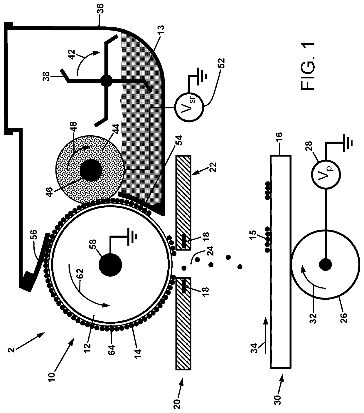
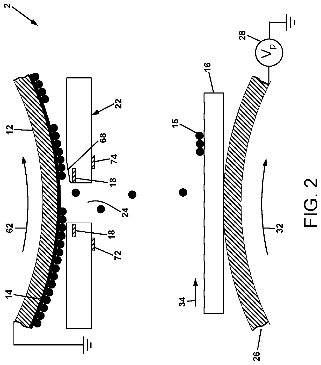
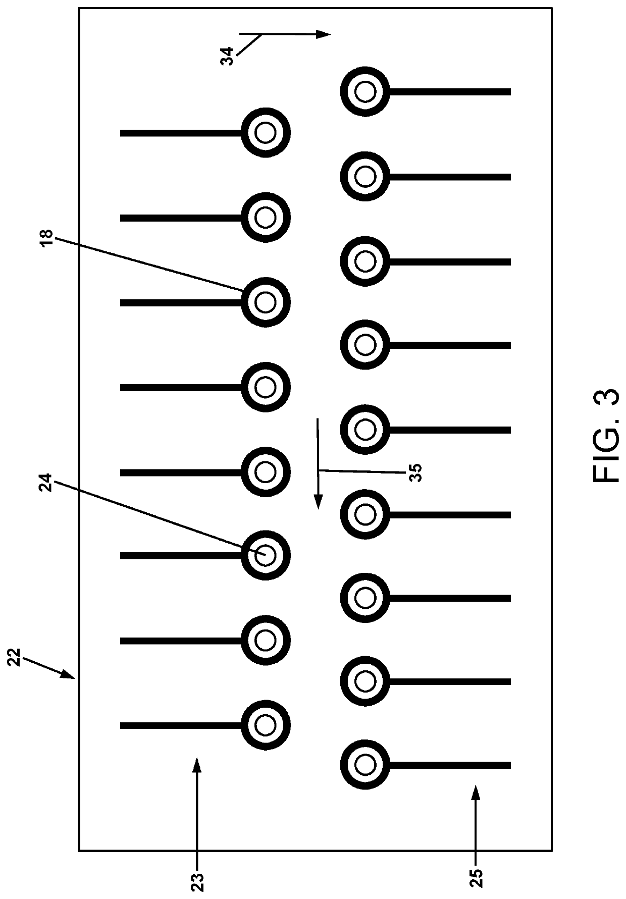
[0047]For a general understanding of the present invention, reference is made to the drawings. In the drawings, like reference numerals have been used throughout to designate identical elements. It is to be understood that the overall scale of the drawings and the relative sizes of particular features are as shown for the sake of clarity of illustration, and may vary from that shown. Additionally, this disclosure may identify certain components with adjectives such as “top,”“upper,”“bottom,”“lower,”“left,”“right,” etc. These adjectives are provided in the context of the orientation of the drawings, which is not to be construed as limiting the apparatus disclosed herein to use in a particular spatial orientation.

[0048]It is also to be understood that any connection references used herein (e.g., attached, coupled, connected, and joined) are to be construed broadly and may include intermediate members between a collection of elements and relative movement between elements unless otherw...


PUM

PropertyMeasurementUnit
sizeaaaaaaaaaa
sizeaaaaaaaaaa
thickaaaaaaaaaa

Abstract

A method of fabricating an object, comprising direct depositing a first layer of first object material on a support substrate electrode; applying a conductive agent material onto the first layer; direct depositing a first layer of charged powder onto the first layer on the support substrate electrode, to form a first powder layer on the first layer on the support substrate electrode. Multiple powder layers may be direct deposited on the first layer. The method may be further comprised of fusing the powder layer(s) to form a first fused layer on the support substrate electrode. A related object fabrication apparatus is also disclosed.

Description

CROSS-REFERENCE TO RELATED PATENT APPLICATIONS[0001]This application claims the benefit of U.S. Provisional Patent Application No. 62 / 443,007 filed Jan. 6, 2017, the disclosure of which is incorporated herein by reference. This application is also related to commonly owned copending U.S. patent application Ser. No. 15 / 050,729 filed on Feb. 23, 2016, and U.S. Provisional Patent Application No. 62 / 440,487 filed on Dec. 30, 2016, the disclosures of which are incorporated herein by reference.BACKGROUNDTechnical Field[0002]Devices for and methods of fabrication of three-dimensional objects from powder starting materials.Description of Related Art[0003]This disclosure relates to a process and apparatus for more efficiently manufacturing three-dimensional (3D) objects from powder materials using a digital multilayer fabrication method. The 3D manufacturing process, also known as additive manufacturing, rapid prototyping or solid freeform, uses digital files that describe cross sections for...

Claims


Application Information

Patent Timeline
Patent Type & Authority Patents(United States)
IPC IPC(8): B29C64/165B22F3/15B29C64/209G03G15/02B29C64/176B33Y30/00B22F3/00B29C64/245B05D1/04
CPCB29C64/165B22F3/003B22F3/156B29C64/176B29C64/209B29C64/245B33Y30/00G03G15/0241B05D1/045G03G15/224G03G15/346B22F10/25B22F2999/00B33Y50/02B22F12/50B22F12/57B29C64/343B29C64/329Y02P10/25B22F10/30B22F2202/06
Inventor HAYS, DAN A.MASON, PETER J.
Owner XACTIV
Why Eureka
Try Eureka