Method of manufacturing liquid ejection head
a technology of liquid ejection and manufacturing method, which is applied in the direction of printing, chemistry apparatus and processes, inking apparatus, etc., can solve the problems of large step difference generated at the connection portion between the element substrates adjacent to each other, deterioration of the bonding accuracy of the element substrates to the base material, and inability to meet the requirements of parts with desired accuracy, etc., to achieve the effect of reducing the cost of a liquid ejection head, small thermal linear expansion coefficien
- Summary
- Abstract
- Description
- Claims
- Application Information
AI Technical Summary
Benefits of technology
Problems solved by technology
Method used
Image
Examples
first embodiment
[0021]In the present embodiment, a method of manufacturing a page-wide (line) liquid ejection head in which a plurality of element substrates for ejecting a liquid such as ink is arranged on a base material (support member) in in-line form (linearly) will be described. The constitution of the liquid ejection head in the present invention is not limited to that described in the following embodiments but it may have a plurality of element substrates arranged in zigzag form on a base material. The liquid ejection head is not limited to a line head (liquid ejection head) insofar it has a plurality of element substrates arranged thereon and it may be a scanning type head that scans in a direction crossing the conveying direction of a recording medium such as paper.
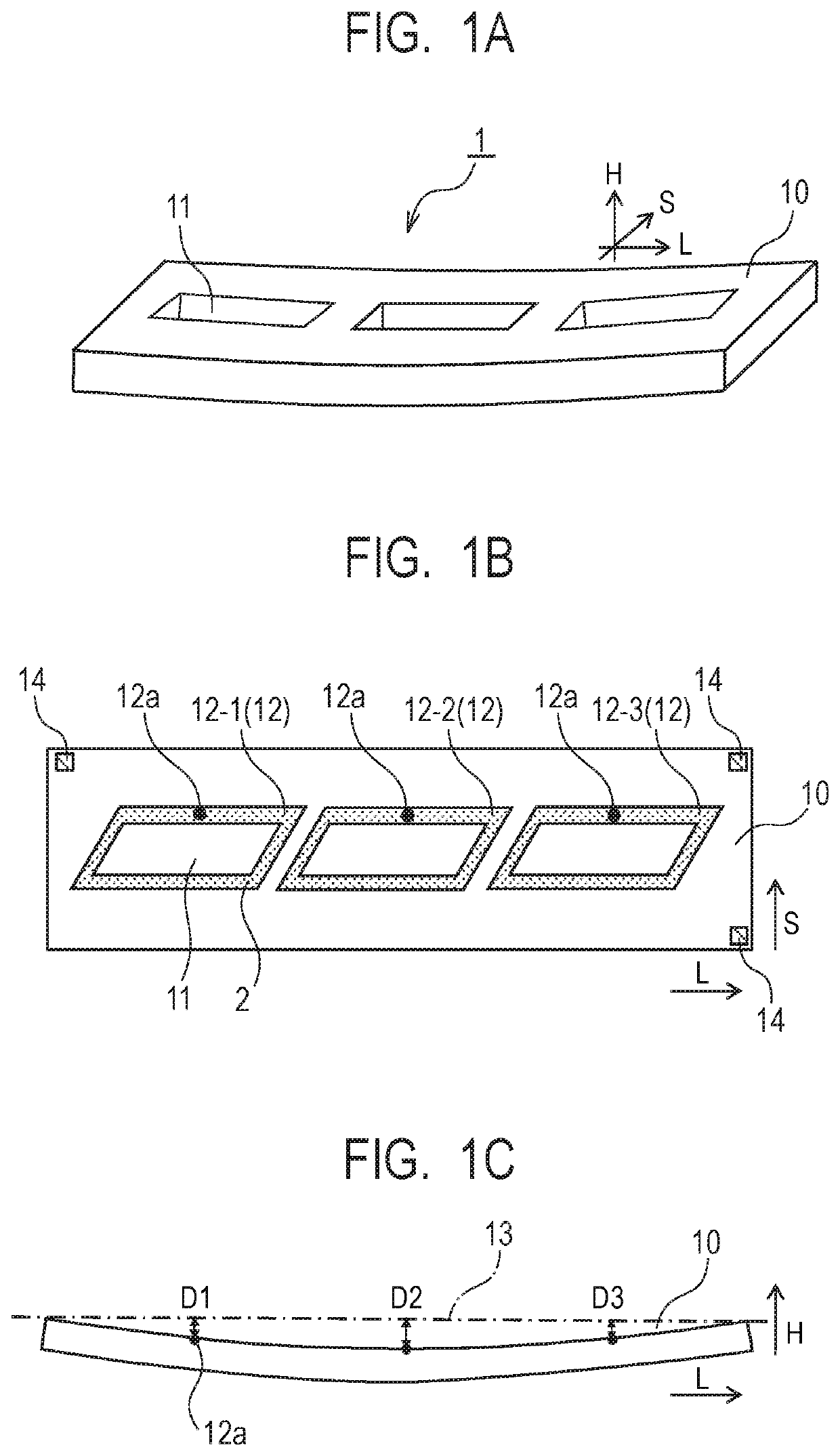
[0022]FIGS. 1A to 1C show a base material of the present embodiment. FIG. 1A is a perspective view showing the base material, FIG. 1B is a top view of the base material shown in FIG. 1A and FIG. 1C is a side view of the base ma...
second embodiment
[0058]FIGS. 5A to 5C show the base material in the present embodiment. More specifically, FIG. 5A is a perspective view showing the base material, FIG. 5B is a top view of the base material shown in FIG. 5A and FIG. 5C is a side view of the base material shown in FIG. 5A.
[0059]The base material 1 of the present embodiment shown in FIGS. 5A to 5C is different from the base material 1 of First Embodiment shown in FIGS. 1A to 1C in that the former one has five supply ports 11 and has a bonding surface 10 having a convex warp (a warp of the bonding surface 10 has a convex shape when viewed from the shorter direction, that is, S direction of the base material 1) at normal temperatures. The base material in the present embodiment has five supply ports 11 so that it has five bonding regions 12. In order to distinguish these five bonding regions 12, they will hereinafter be called “bonding regions 12-1 to 12-5”, respectively, in the order from left to right in FIG. 5B.
[0060]The height of th...
third embodiment
[0070]FIG. 7 is a side view showing a base material of the present embodiment. The base material 1 of the present embodiment shown in FIG. 7 is different from the base material 1 in First Embodiment shown in FIG. 1C in that the former base material 1 has a warp having an S shape when viewed from the shorter direction, that is, S direction of the base material 1.
[0071]Also in the present embodiment, the height of the bonding region 12 is defined by a reference distance between a virtual reference plane 13 serving as a reference of the bonding surface 10 in the ejecting direction H and a middle point 12a of the bonding region 12 in the L direction. In the present embodiment, supposing that reference distances to the bonding regions 12-1 to 12-3 are D1 to D3, respectively, the reference distances D1 to D3 have the following relationship: D1>D2>D3. Also in the present embodiment similar to First Embodiment, the bonding step is performed for the bonding regions 12-1 to 12-3 in an ascendi...
PUM
| Property | Measurement | Unit |
|---|---|---|
| distance D2 | aaaaa | aaaaa |
| temperature | aaaaa | aaaaa |
| shape | aaaaa | aaaaa |
Abstract
Description
Claims
Application Information
 - R&D
- Intellectual Property
- Life Sciences
- Materials
- Tech Scout
- Unparalleled Data Quality
- Higher Quality Content
- 60% Fewer Hallucinations
Browse by: Latest US Patents, China's latest patents, Technical Efficacy Thesaurus, Application Domain, Technology Topic, Popular Technical Reports.
© 2025 PatSnap. All rights reserved.Legal|Privacy policy|Modern Slavery Act Transparency Statement|Sitemap|About US| Contact US: help@patsnap.com


