Method of joining structures made of incompatible polymers

a polymer and polymer technology, applied in the field of joining structures made of incompatible polymers, can solve the problems of inability to meet the requirements of the etfe buffer layer,

Active Publication Date: 2021-11-16
OPTICAL INTEGRITY INC
View PDF4 Cites 0 Cited by
  • Summary
  • Abstract
  • Description
  • Claims
  • Application Information

AI Technical Summary

Benefits of technology

[0019]The option of using the welded raised structures as threads or nubs for a threaded, bayonet, pin-and-slot, snap-fit, or similar connection enables the second structure to be removed from the first structure and replaced whenever the second structure becomes worn during use. In addition, a threaded connection has the advantage of enabling axial adjustment of a distance or set back between the distal end of the protective tip and the distal end of the fiber, by rotating the protective tip.

Problems solved by technology

Some polymers will not chemically bond to each other and cannot be welded.
As a result, attachment of soft fiber tip protective structures to fibers having ETFE buffer layers by welding or chemical bonding is currently considered to be impractical from standpoints of manufacturing efficiency and cost.
However, each alternative method has disadvantages in terms of safety and performance of the finished product.
U.S. Pat. No. 6,282,349 (Griffin) includes a detailed discussion of the disadvantages of using adhesives to attach a quartz ferrule to a fiber, including contamination by the outgassing adhesive of the laser output lens and the possibility of sudden, explosive failure of the fiber termination as well as low yield if the viscosity of the adhesive is increased to avoid outgassing or the ferrule is countersunk to move the adhesive away from the end of the fiber.
In addition, the Griffin patent discusses the disadvantages of crimping the ferrule directly to the fiber, including lowered connector mass and incompatibility with surgical laser interlocks.
These disadvantages also apply to attachment of polymeric protective structures rather than quartz ferrules, but Griffin's solution of crimping the fiber into a cylindrical beam block extension is suitable only for rigid structures such as a quartz ferrule, and not for attachment of soft polymer protective structures such as the ones disclosed in PCT Publication No.

Method used


Image

  • Method of joining structures made of incompatible polymers

Examples


Embodiment Construction

[0022]Throughout the following description and drawings, like reference numbers / characters refer to like elements. It should be understood that, although specific exemplary embodiments are discussed herein there is no intent to limit the scope of present invention to such embodiments. To the contrary, it should be understood that the exemplary embodiments discussed herein are for illustrative purposes, and that modified and alternative embodiments may be implemented without departing from the scope of the present invention.

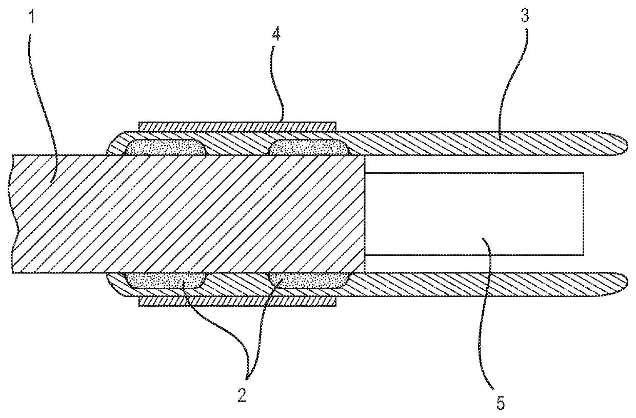
[0023]As illustrated in FIG. 1, a surgical laser fiber is stripped to expose a buffer layer 1 and a core or core / cladding section 5. A soft protective structure 3 having a generally cylindrical shape is to be attached to the end section of the buffer layer 1. The soft protective structure 3 may have a standoff structure of the type disclosed in PCT Publication No. WO 2017 / 192869 or Provisional Patent Appl. Ser. No. 62 / 648,108, in which the distal end of the protec...


PUM

PropertyMeasurementUnit
structureaaaaaaaaaa
viscosityaaaaaaaaaa
distanceaaaaaaaaaa

Abstract

A first structure made of a first polymer is joined to a second structure made of an incompatible second polymer by the steps of welding small bands of compatible tubing or material to the first structure to create raised structures or ribs, and mechanically linking the second structure with the ribs or raised structures at the desired attachment point. The mechanical linkage may be accomplished by using heat shrinking or mechanical compression (such as crimping) to force the incompatible second polymer around the ribs or raised structures or, in the case of raised structures formed as threads or nubs, by inter-engagement between the threads or nubs on the first structure and corresponding structures, such as internal threading, nub-receiving slots, or internal surfaces, of the second structure. The option of using the welded raised structures as threads or nubs for a threaded, bayonet, pin-and-slot, snap-fit, or similar connection enables the second structure to be removed from the first structure and replaced whenever the second structure becomes worn during use. The first structure may be an surgical laser fiber with an ETFE buffer layer, and the second structure is a protective structure may be made of PTFE, PET, FEP or PFA.

Description

BACKGROUND OF THE INVENTION1. Field of the Invention[0001]The invention relates to a method of joining incompatible polymers.[0002]The method of the invention may be used, by way of example and not limitation, to attach a PTFE, PET, FEP, or PFA fiber tip protective structure to an ETFE buffer of a surgical laser fiber.[0003]The invention also relates to a product made by the method of the invention, and to an arrangement for removably coupling a protective tip to an surgical laser fiber.2. Description of Related Art[0004]Some polymers will not chemically bond to each other and cannot be welded. For example, the fiber buffer of a surgical laser optical fiber is often made of ethylene tetrafluoroethylene (ETFE), while fiber tip protective structures such as the ones disclosed in the inventor's PCT Publication No. WO 2017 / 192869 and Provisional Patent Appl. Ser. No. 62 / 648,108, filed Mar. 26, 2018, and incorporated herein by reference, may be made of a soft polymer such as polytetraflu...

Claims


Application Information

Patent Timeline
Patent Type & Authority Patents(United States)
IPC IPC(8): B29C65/02A61B18/22B29C65/00B29K67/00B29K27/18
CPCB29C65/02A61B18/22B29C66/71A61B2018/2222B29K2027/18B29K2067/003B29C65/561B29C65/565B29C65/58B29C65/68B29C65/76B29C66/02B29C66/1122B29C66/526B29C66/5261B29C66/534B29C66/712B29C66/73921B29C66/81471B29K2023/08B29K2027/12
Inventor MALPHURS, DANIEL
Owner OPTICAL INTEGRITY INC
Why Eureka
Try Eureka