
Method and apparatus for additive manufacturing

a technology of additive manufacturing and manufacturing method, applied in the direction of additive manufacturing process, manufacturing tool, manufacturing driving means, etc., can solve the problems of dimension errors, reduce mechanical properties of final articles, etc., and achieve the effect of sacrificing material properties of final products and efficient building of higher quality parts

Active Publication Date: 2021-11-30
ARCAM AB
View PDF311 Cites 0 Cited by
  • Summary
  • Abstract
  • Description
  • Claims
  • Application Information

AI Technical Summary

Benefits of technology

[0008]An object of the present invention is to provide an additive manufacturing apparatus and method suitable for additive manufacturing of three-dimensional parts which is capable of efficiently building higher quality parts than prior art machines without sacrificing material properties of the final product.
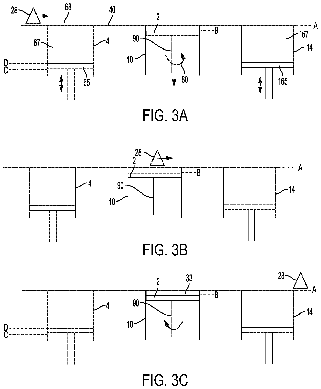
[0010]An exemplary advantage of at least these embodiments is that additive manufacturing may be performed with higher yield. This is due to the fact that the angle of the manufactured part(s) relative to the powder distributor is not constant but changed from one layer to another. This will help removing repetitive errors that may arise when using a static angle between the parts that is to be manufactured and the powder distributor. By changing the angle of the powder distribution mechanism and the support structure onto which the three-dimensional article is manufactured may also remove errors in the powder distribution process independently of what is manufactured, i.e., powder distribution errors are distributed more evenly over the manufacturing area compared to when using a fixed angle of the powder distribution process and support structure. In the latter case, errors may be stacked onto each other from one layer to another, which in the end may cause not only dimension errors but also reduced mechanical properties of the final article.
[0012]An exemplary advantage of using unequal rotational angle from one layer to another is that errors emanating from the powder distribution process is spread out at a larger area where they have no impact on the final article or eliminated due to the fact that the angle between the powder distributor and the previously built three-dimensional layer will not cause any powder layer inhomogeneities. An exemplary advantage of using an equal rotational angle for a predetermined number of layers is that the angle is known beforehand not to cause any powder layer inhomogeneities for the-three dimensional cross sections which is to be built. Another fixed rotational angle may be used for a predetermined number of layers if the other rotational angle gives a better powder layer homogeneity than the previously used rotational angle. A more favourable rotational angle may arise if the cross sections which has been built is altered.
[0014]An exemplary advantage of rotating the support structure alone and keeping the position of the build tank fixed is that it reduces the mechanical complexity of the machine. An exemplary advantage of rotating the build tank is that it may reduce the leakage of powder between the support structure and the build tank.
[0015]An advantage of various example embodiments of the present invention is that any type of powder distribution process may be used. The rotation of the support structure a predetermined angle before powder application and then reposition to the original position before fusion takes place may reduce powder distribution related errors irrespective of how the powder distribution is made.
[0017]An exemplary advantage of at least these embodiments is that it provides for an additive manufacturing apparatus with higher yield. This is due to the fact that the angle of the manufactured part(s) relative to the powder distributor is not constant but changed from one layer to another. This will help removing repetitive errors that may arise when using a static angle between the parts that is to be manufactured and the powder distributor. By changing the angle of the powder distribution mechanism and the support structure onto which the three-dimensional article is manufactured may also remove errors in the powder distribution process independently of what is manufactured, i.e., powder distribution errors are distributed more evenly over the manufacturing area compared to when using a fixed angle of the powder distribution process and support structure. In the latter case, errors may be stacked onto each other from one layer to another, which in the end may cause not only dimension errors but also reduced mechanical properties of the final article.

Problems solved by technology

In the latter case, errors may be stacked onto each other from one layer to another, which in the end may cause not only dimension errors but also reduced mechanical properties of the final article.

Method used


Image

  • Method and apparatus for additive manufacturing
  • Method and apparatus for additive manufacturing
  • Method and apparatus for additive manufacturing

Examples


Embodiment Construction

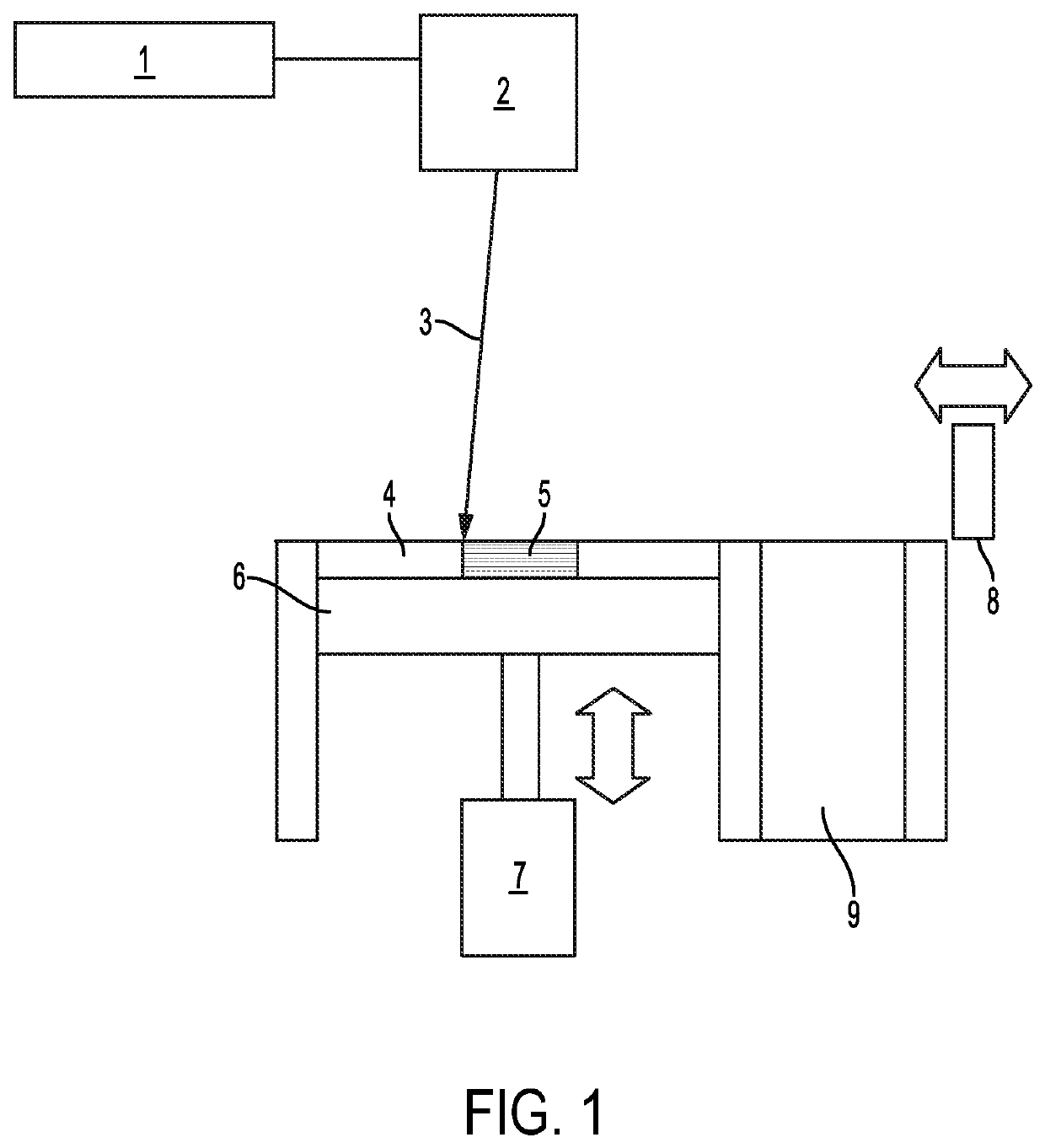
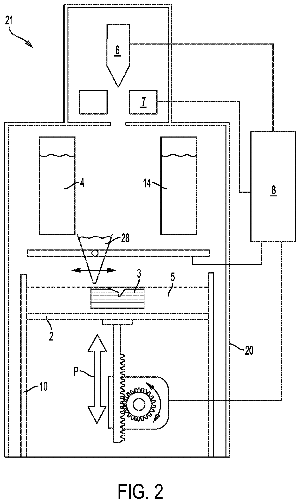
[0032]Various example embodiments of the present invention will now be described more fully hereinafter with reference to the accompanying drawings, in which some, but not all embodiments of the invention are shown. Indeed, embodiments of the invention may be embodied in many different forms and should not be construed as limited to the embodiments set forth herein. Rather, these embodiments are provided so that this disclosure will satisfy applicable legal requirements. Unless otherwise defined, all technical and scientific terms used herein have the same meaning as commonly known and understood by one of ordinary skill in the art to which the invention relates. The term “or” is used herein in both the alternative and conjunctive sense, unless otherwise indicated. Like numbers refer to like elements throughout.

[0033]To facilitate the understanding of this invention, a number of terms are defined below. Terms defined herein have meanings as commonly understood by a person of ordinar...


PUM

PropertyMeasurementUnit
angleaaaaaaaaaa
accelerating voltageaaaaaaaaaa
angleaaaaaaaaaa

Abstract

A method for forming at least one three-dimensional article through successive fusion of parts of a powder bed on a support structure, the method comprising the steps of: providing at least one model of the three-dimensional article, lowering the support structure a predetermined distance and rotating the support structure a predetermined angle in a first direction before applying a first powder layer covering the lowered and rotated support structure, rotating the support structure the predetermined angle in a second direction opposite to the first direction before directing the at least one first energy beam from the at least one first energy beam source at selected locations of the first powder layer, the at least one first energy beam source causing the first powder layer on the stationary support structure which is stationary to fuse in the selected locations according to the model to form first portions of the three-dimensional article.

Description

CROSS REFERENCE TO RELATED APPLICATIONS[0001]This application claims benefit of U.S. Provisional Patent Application No. 62 / 565,596, filed on Sep. 29, 2017, the contents of which as are hereby incorporated by reference in their entirety.BACKGROUNDTechnical Field[0002]The present invention relates to a method and apparatus for additive manufacturing of 3-dimensional objects.Related Art[0003]Freeform fabrication or additive manufacturing is a method for forming three-dimensional articles through successive fusion of chosen parts of powder layers applied to a work plate.[0004]Such an apparatus may comprise a work plate on which the three-dimensional article is to be formed, a powder dispenser, arranged to lay down a thin layer of powder on the work plate for the formation of a powder bed, a laser beam source for delivering energy to the powder whereby fusion of the powder takes place, elements for control of the laser beam source over the powder bed for the formation of a cross section ...

Claims


Application Information

Patent Timeline
Patent Type & Authority Patents(United States)
IPC IPC(8): B22F12/00B29C64/245B29C64/153B29C64/241B33Y10/00B33Y30/00B23K26/08B33Y50/02B22F3/10B22F10/10
CPCB22F12/00B22F3/1017B23K26/083B23K26/0823B29C64/153B29C64/241B29C64/245B33Y10/00B33Y30/00B33Y50/02B22F10/10B29C64/20Y02P10/25B22F12/37B22F10/362B22F12/13B22F12/55B22F10/32B22F10/28B22F12/52B22F12/90B22F10/36
Inventor HELLESTAM, CALLE
Owner ARCAM AB
Learn More