Gas turbine engine exhaust nozzle

a technology of exhaust nozzle and gas turbine engine, which is applied in the direction of marine propulsion, vessel construction, aircraft navigation control, etc., can solve the problems of difficult actuation, excessive drag, and relatively heavy arrangement of nozzles, and achieves the effect of improving the aerodynamic profile of the nozzle arrangement, and reducing the number of nozzles

Inactive Publication Date: 2014-05-29
ROLLS ROYCE PLC
View PDF16 Cites 4 Cited by
  • Summary
  • Abstract
  • Description
  • Claims
  • Application Information

AI Technical Summary

Benefits of technology

[0017]The closure element may comprise overlapping radially inner and radially outer closure members which may define a chamber therebetween. One of the radially inner and outer closure members may be movable between the open and closed positions by an actuator, and the other of the radially inner and outer members may be moveable between the open and closed positions by a pressure differential across the respective closure member. By providing inner and outer closure members, the thickness of the closure element (i.e. the distance between the outer surface of the outer closure member, and the inner surface of the inner closure member) can be relatively large, while the individual closure members can be relatively thin, and therefore relatively flexible and light, and so require relatively little force to actuate. Due to the pressure gradient introduced by opening one of the closure members, the other closure member is forced to open, and so only one of the closure members may require an actuator. On the other hand, the thickness of the closure element may improve the aerodynamic profile of the nozzle arrangement, since the thickness of the closure element can be made to match the thickness of the remainder of the outer wall.
[0018]A downstream end of the downstream outer wa

Problems solved by technology

As a result, such arrangements have been found to be relatively heavy and difficult to actuate.
The large length of the tabs may also cause excessive drag when deployed.
Consequently, such arrangements may have a net negative performance benefit where the bypass ratio is less than 10:1 and only a slight benefit at higher bypass ratios.
However, such an arrangement has been found to be h

Method used


Image

  • Gas turbine engine exhaust nozzle
  • Gas turbine engine exhaust nozzle
  • Gas turbine engine exhaust nozzle

Examples


Embodiment Construction

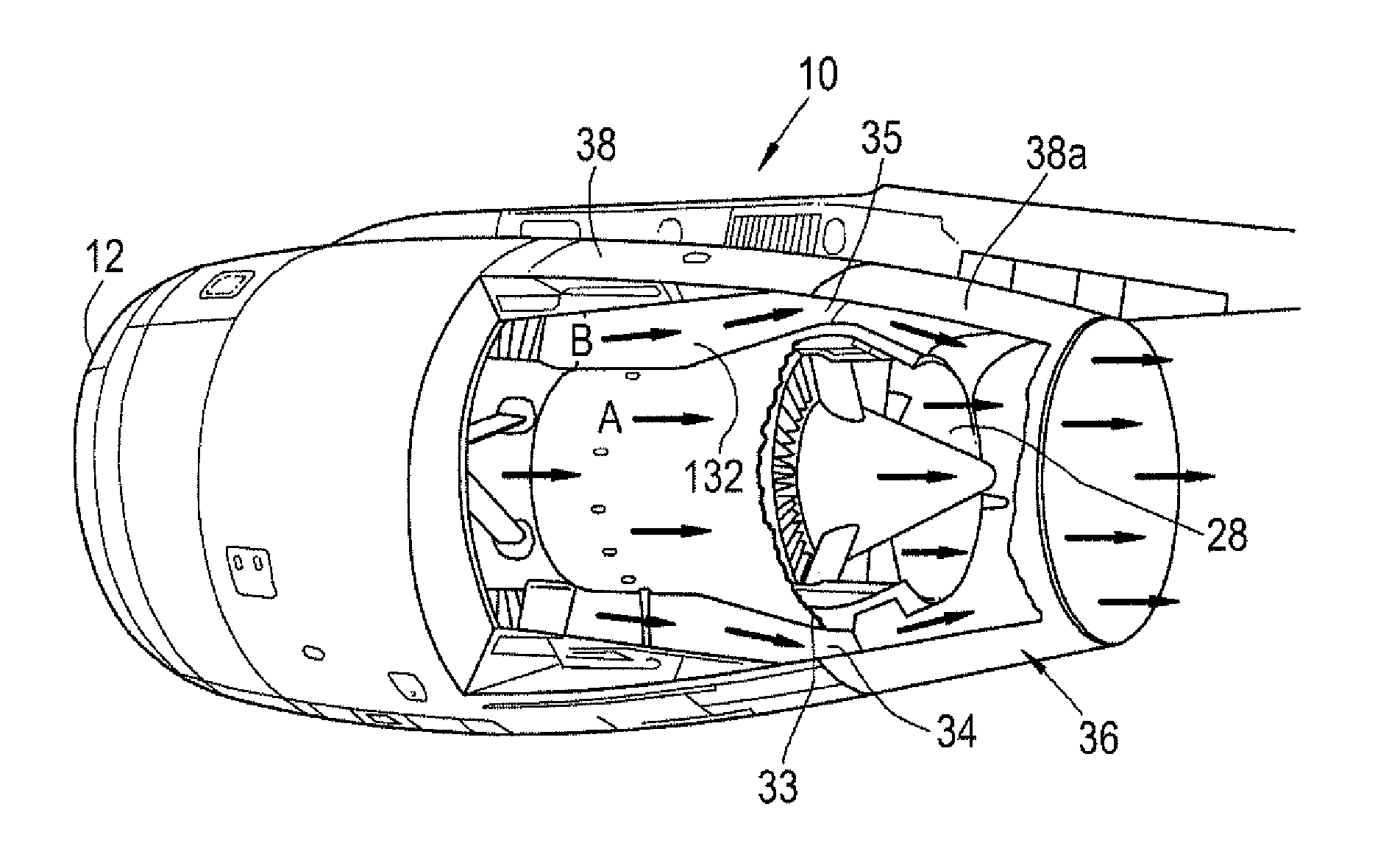
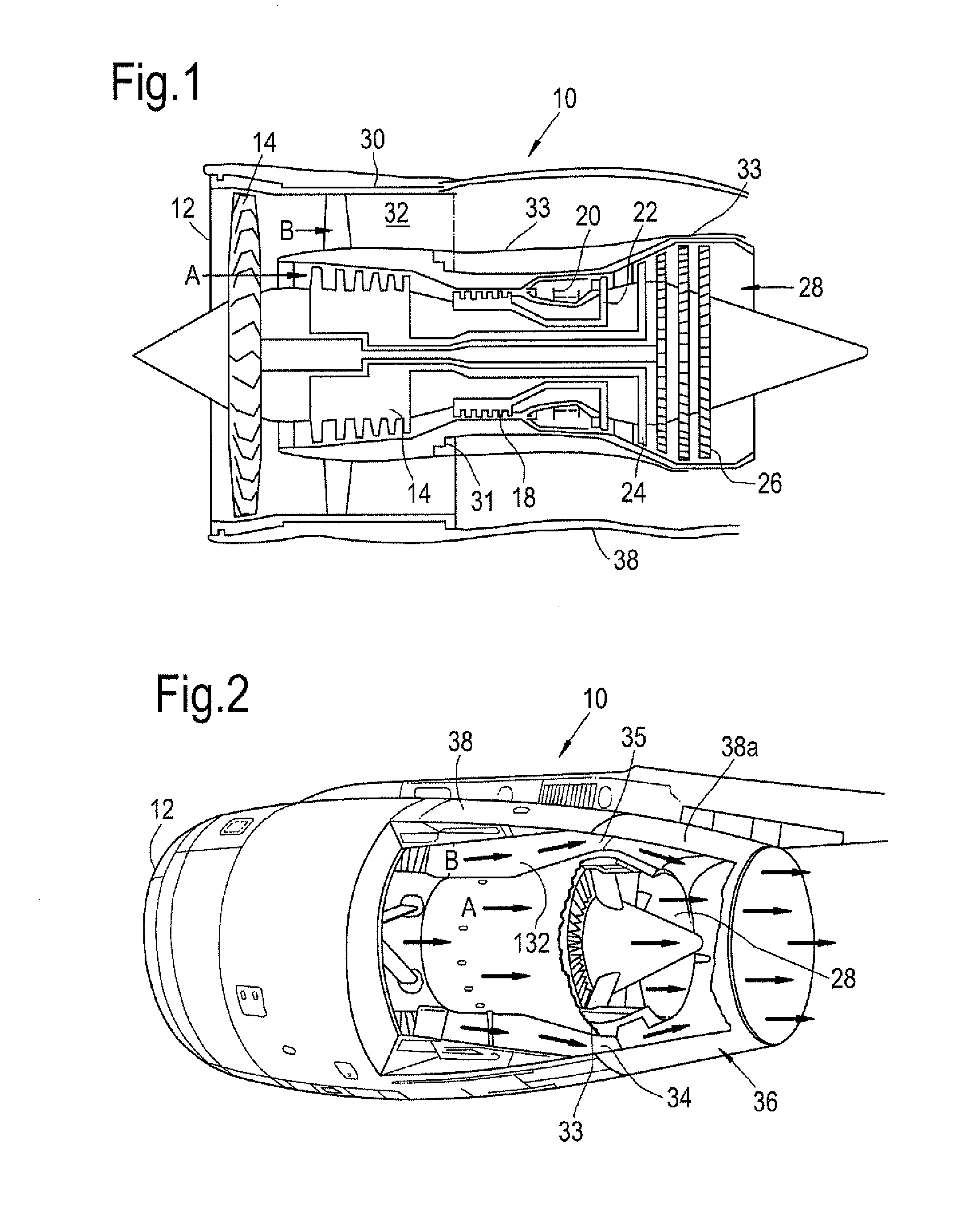
[0030]A first bypass gas turbine engine 10 is shown in FIG. 1 and comprises an air intake 12 and a propulsive fan 14 that generates two airflows A and B. The gas turbine engine 10 comprises, in axial flow A, an intermediate pressure compressor 16, a high pressure compressor 18, a combustor 20, a high pressure turbine 22, an intermediate pressure turbine 24, a low pressure turbine 26 and a core exhaust nozzle 28. Each of the compressors 16, 18 and turbines 22, 24, 26 are housed within a core casing 31. The core casing 31 includes a turbine casing 33 which houses the turbines 22, 24, 26, and a compressor casing 37 which houses the compressors 16, 18. The turbine casing 33 has a generally frusto-biconical shape such that the casing 33 diverges outwardly in a downstream direction from an upstream end to an inflection point, and then converges inwardly. The radial extent of the turbine casing 33 therefore increases from the upstream end in a downstream direction to accommodate the increa...


PUM


Abstract

An exhaust nozzle 234 comprising inner and outer walls defined by a turbine casing 233 and a nacelle 230 respectively. A duct in the form of a bypass duct 232 is defined therebetween through which a bypass flow B flows in use. The nacelle 230 comprises a fixed upstream wall section 240 and at least one radially movable downstream wall section 242. At least one closure element in the form of a first slat 248 is provided, which is locatable across the second outlet 246 extending in a generally axial direction. A downstream end 250 of the first slat 248 is radially moveable between an open position in which the second outlet 246 is open, and a closed position in which the second outlet 246 is closed.

Description

FIELD OF THE INVENTION[0001]The present invention relates to a gas turbine engine exhaust nozzle, and in particular to a variable area gas turbine engine exhaust nozzle.BACKGROUND TO THE INVENTION[0002]Gas turbine engines are widely used to power aircraft. As is well known, the engine provides propulsive power by generating a high velocity stream of gas which is exhausted rearwards through an exhaust nozzle. A single high velocity gas stream is produced by a turbo jet gas turbine engine. Alternatively, two streams, a core exhaust and a bypass exhaust, are generated by a ducted fan gas turbine engine (also known as a bypass gas turbine engine).[0003]The optimum area of the nozzle exit of a gas turbine engine exhaust nozzle depends on a variety of factors, such as the ambient conditions of temperature and pressure, and the mass flow of exhaust gas, which depends on the operating condition of the engine. Aircraft engines spend a substantial proportion of their life at cruise (i.e. at h...

Claims


Application Information

Patent Timeline
IPC IPC(8): F02K1/12
CPCF02K1/1207F02K1/085F02K1/50
Inventor WEBSTER, JOHN RICHARD
Owner ROLLS ROYCE PLC
Why Eureka
Try Eureka