Aspiration smoke detection system

a smoke detection and air intake technology, applied in the direction of fire alarm smoke/gas actuation, fire alarms, instruments, etc., can solve the problems of not enough smoke or heat to be detected by the local sensor, produce a small amount of smoke and/or heat, and produce enough smoke, so as to reduce the detection time, detect certain fires more quickly, and determine the location of fires more quickly

Active Publication Date: 2021-11-30
CARRIER CORP
View PDF13 Cites 0 Cited by
  • Summary
  • Abstract
  • Description
  • Claims
  • Application Information

AI Technical Summary

Benefits of technology

[0009]By providing an aspiration smoke detection unit with both a smoke detection unit and one or more local sensors, the system is able to detect certain fires more quickly, and may allow for determination of the location of a fire more quickly. The local sensors allow early response on quick developing fires and may allow the provision of an aspiration smoke detection system with addressability.
[0010]The local sensors can be used to detect a quickly developing fire before a sample from the fire reaches the central smoke detection unit, hence decreasing the detection time. That is to say, quick developing fires can be detected by a local sensor in a time that is shorter than the time it takes for a sample from the location of the fire to reach the smoke detection unit. Advantageously, the system allows for quick developing fires and / or explosions etc. to be detected more quickly compared to a system without local sensors.
[0026]This may allow removal of the inlet piece, and hence associated local sensor. This may allow repair, replacement and / or charging of the local sensor without having to remove or disable the aspiration smoke detection system, and in particular without having to remove or disable the smoke detection unit.
[0043]The greater the distance the larger the region of interest that may be monitored may be. The presence of both a central smoke detection unit and one or more local sensors may be particularly beneficial when the region of interest is large. This is because the time for a sample to enter one of the inlets and then reach the central smoke detection unit may be greater. In this case, the local sensor can be used to detect a quickly developing fire before a sample from the fire reaches the central smoke detection unit, hence decreasing the detection time. Additionally, if the central smoke detector detects a fire, in the case that the system comprises a plurality of local sensors, data from the local sensors can be analysed to determine at which location the fire is most likely to be located. This can be particularly beneficial when the region of interest is large and there may be a large number of inlets from which the sample may have originated.
[0049]If the data from the smoke detection unit is indicative of a fire being present in the region of interest, the controller may be configured to determine the most likely location of a fire within the region of interest based on data collected by the local sensors. The controller may be arranged to analyse the data from the local sensors to determine whether any of them has detected a change in the measured property of air, e.g. a change in the temperature, a change in the concentration of smoke particles in the air and / or a change in the CO2 level etc. If a plurality of the local sensors has detected a change, the controller may be arranged to determine which of the sensors has detected the greatest change. The location at the local sensor with the greatest change may be assessed first to determine if a fire is present at that location. The controller may determine an order in which locations (e.g. rooms) within the region of interest should be checked based on the data from the local sensors. Whilst the detected change at the local sensors may be very small and hence not sufficient on its own to suggest the presence of a fire, it may still usefully be used as an indication of the most likely location for the fire. Thus, this may potentially allow the fire to be located more quickly.
[0052]By performing both a step of determining if the concentration of smoke particles measured by the smoke detection unit is indicative of a fire within the region of interest and a step of determining if the measured property of air sensed by the one or more local sensors is indicative of a fire within the region of interest, fires may be detected more quickly. This is because quick developing fires can be detected by the one or more local sensors before a sample reaches the smoke detection unit and slow developing fires may be detected by the smoke detection unit before the impact on the environment is great enough to be detected by the local sensors. This is because the smoke detection unit may be more sensitive than the local sensors.

Problems solved by technology

Some fires, such as slow developing fires, may, at least at the start of the fire, only produce a small amount of smoke and / or heat.
This may produce enough smoke to be detected by the smoke detection unit but not enough smoke or heat to be detected by the local sensor.

Method used


Image

  • Aspiration smoke detection system

Examples


Embodiment Construction

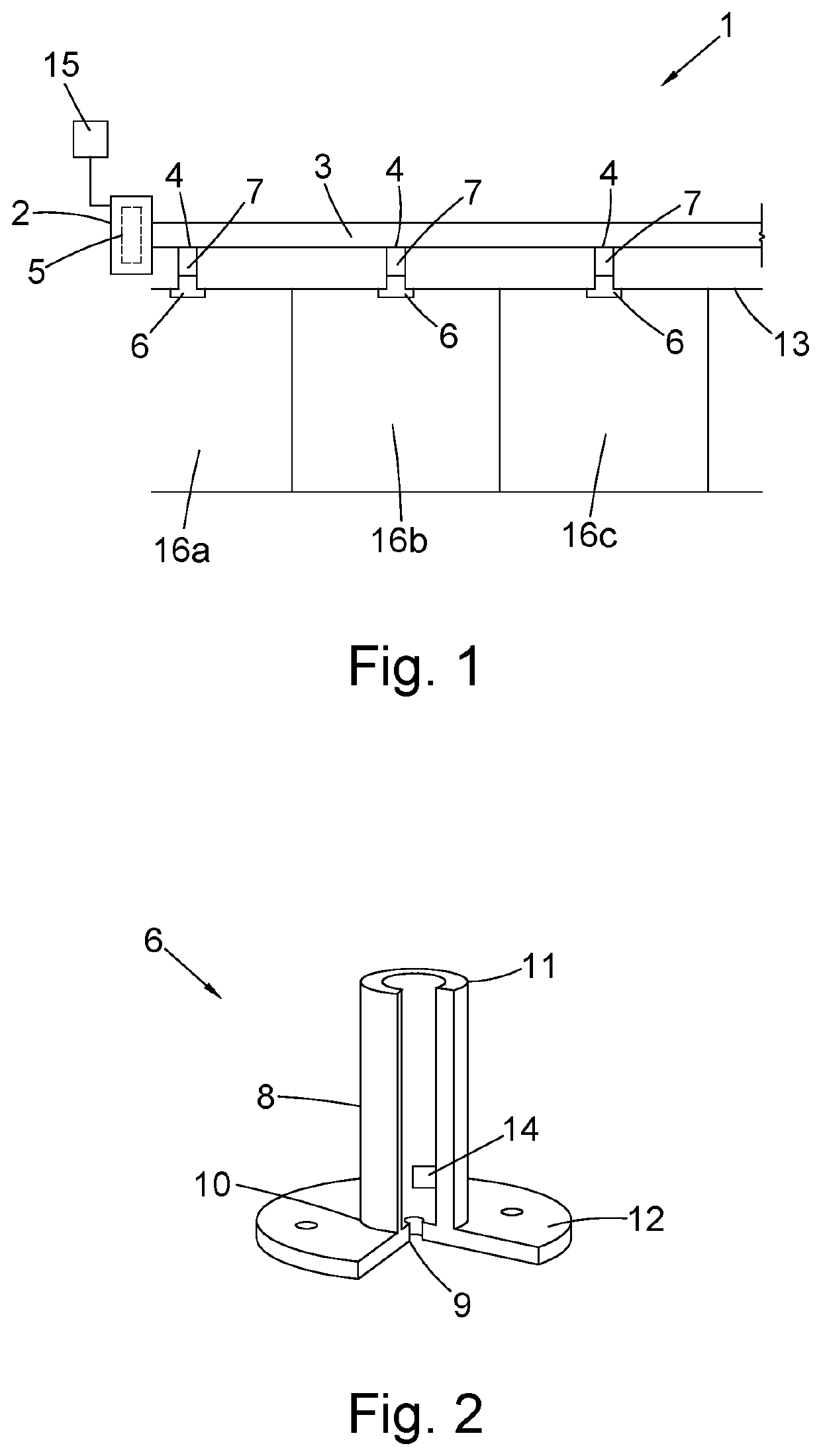
[0069]FIG. 1 shows an aspiration smoke detection system 1 capable of detecting the presence of a fire within a region of interest, for instance one or more rooms 16a, 16b, 16c of a building. The system 1 comprises a central detection unit 2 and a sampling pipe 3 extending from the central detection unit 2 for enabling air from the region of interest to be passed to the central detection unit 2. A fan, for example, may be used to draw air into the sampling pipe 3 from the region of interest and pass it to the central detection unit 2. In the exemplary embodiment in FIG. 1, the system 1 is shown located and arranged within a ceiling void above several rooms 16a, 16b, 16c in a building in order to detect smoke emanating from within one or more of the rooms 16a, 16b, 16c. However, the aspiration smoke detection system 1 may be used in any location to detect the presence of a fire in a region of interest.

[0070]The central detection unit 2 includes a sampling chamber 5 (shown by the dashe...


PUM


Abstract

An aspiration smoke detection system for detecting the presence of a fire within a region of interest. The aspiration smoke detection system includes a smoke detection unit for detecting the presence of smoke particles suspended in air; and one or more local sensors located remotely from the smoke detection unit for measuring a property of air from the region of interest that is drawn into the aspiration smoke detection system. An inlet piece includes a sensor for use with the aspiration smoke detection system is also provided. A method of detecting a fire using the aspiration smoke detection system and a method of locating a fire using the aspiration smoke detection system are also provided.

Description

FOREIGN PRIORITY[0001]This application claims priority to European Patent Application No. 19383064.3, filed Nov. 29, 2019, and all the benefits accruing therefrom under 35 U.S.C. § 119, the contents of which in its entirety are herein incorporated by reference.TECHNICAL FIELD OF INVENTION[0002]The present invention relates to an aspiration smoke detection system, an inlet piece for the aspiration smoke detection system, a method for detecting a fire using the aspiration smoke detection system, and / or a method of locating a fire using the aspiration smoke detection system.BACKGROUND OF THE INVENTION[0003]An aspiration smoke detection system is a known type of fire detection means. Such systems have a central smoke detection unit. The system is arranged to draw air from a region to be monitored through a series of sampling pipes. The sampling pipes have a plurality of inlets for allowing air (and smoke particles, if present) into the system from a plurality of locations within the reg...

Claims


Application Information

Patent Timeline
Patent Type & Authority Patents(United States)
IPC IPC(8): G08B17/00G08B17/10G08B21/18
CPCG08B17/10G08B21/182G08B25/002
Inventor RIBALDA GALVEZ, MIQUELMUNUERA GARCIA, JOSE MANUELBURRIEL MAUREL, RICARD
Owner CARRIER CORP
Why Eureka
Try Eureka