Cooling system
a cooling system and cooling fan technology, applied in the field of cooling systems, can solve the problems of inconvenient user and time-consuming to switch from the heater cutting mode, and achieve the effect of shortening the time required
- Summary
- Abstract
- Description
- Claims
- Application Information
AI Technical Summary
Benefits of technology
Problems solved by technology
Method used
Image

Examples
first embodiment
[0026]A first embodiment will be described with reference to FIGS. 1 to 4.
[Cooling System]
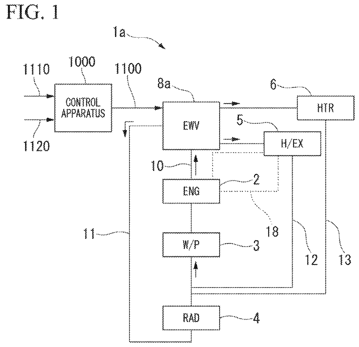
[0027]FIG. 1 is a block diagram of a cooling system 1a.
[0028]As illustrated in FIG. 1, the cooling system 1a is installed in a vehicle including at least an engine in a vehicle driving source. Examples of the vehicle include hybrid vehicles, plug-in hybrid vehicles, and the like in addition to vehicles having only an engine.
[0029]The cooling system 1a is constituted by connecting an engine 2 (ENG), a water pump 3 (W / P), a radiator 4 (RAD), a heat exchanger 5 (H / EX), a heater core 6 (HTR), and a control valve 8a (EWV) through various flow paths 10 to 13.
[0030]The water pump 3, the engine 2, and the control valve 8a are sequentially connected in order from upstream to downstream on the main flow path 10. In the main flow path 10, an operation of the water pump 3 causes cooling water to sequentially pass through the engine 2 and the control valve 8a.
[0031]The main flow path 10 has the radiator f...
second embodiment
[0067]A second embodiment will be described with reference to FIGS. 5A, 5B, 5C and 6.
[0068]The second embodiment is another example of the method of controlling an opening schedule and a control valve. Here, a cooling system associated with the second embodiment will be described below by exemplifying the above-described cooling system 1a illustrated in FIG. 1 associated with the first embodiment.
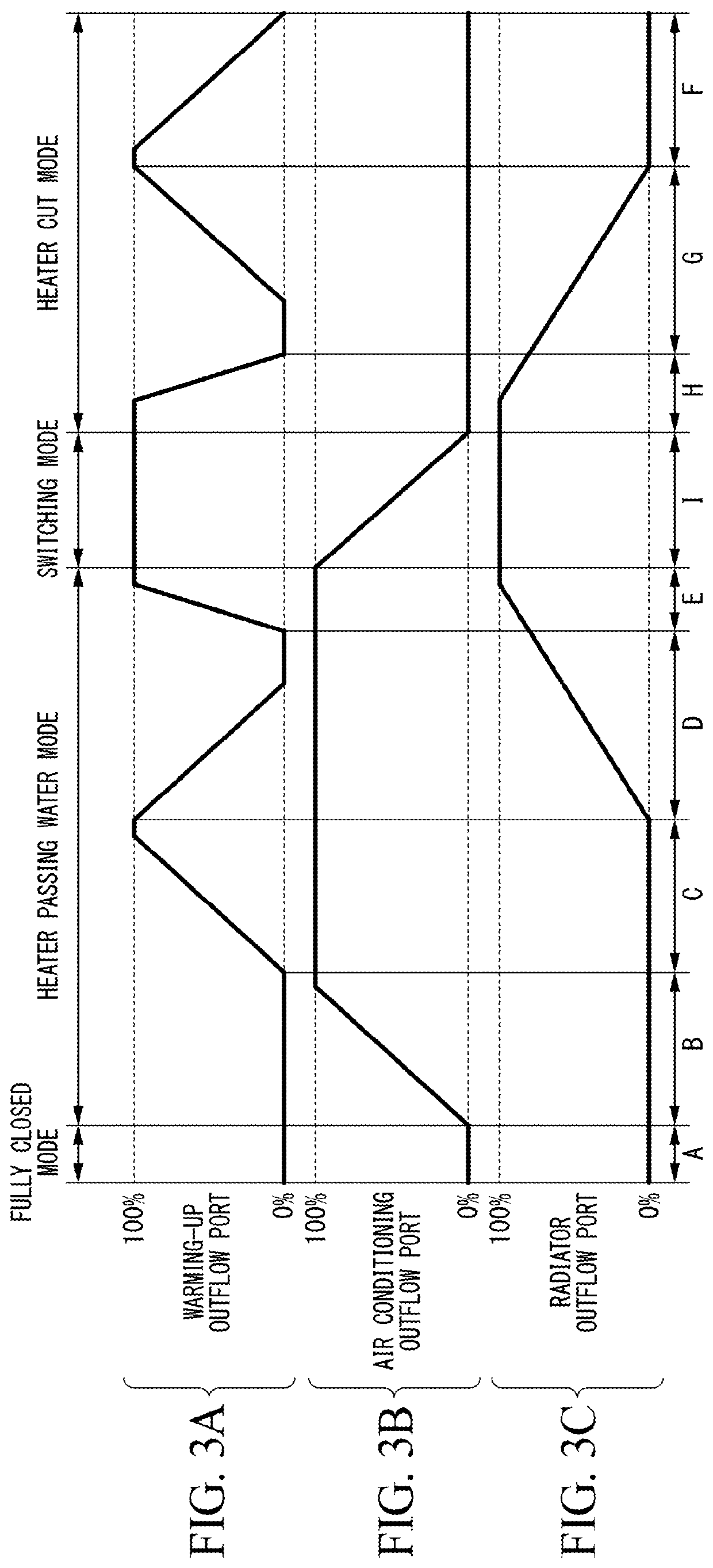
[0069]First, an example of an opening schedule associated with the second embodiment will be described with reference to FIGS. 5A to 5C. FIGS. 5A to 5C are diagrams illustrating an example of the opening schedule.
[0070]Horizontal axes in FIGS. 5A to 5C indicate an operation range of a control valve 8a. Vertical axes in FIGS. 5A to 5C indicate a degree of opening of each outflow port (0% to 100%). FIG. 5A indicates a degree of opening of a warming-up outflow port. FIG. 5B indicates a degree of opening of an air conditioning outflow port. FIG. 5C indicates a degree of opening of a radiator ou...
third embodiment
[0080]A third embodiment will be described with reference to FIGS. 7 to 11.
[Cooling System]
[0081]FIG. 7 is a block diagram of a cooling system 1. Constituent elements in FIG. 7 corresponding to the constituent elements in FIG. 1 will be denoted by the same reference numerals and description thereof will be omitted.
[0082]As illustrated in FIG. 7, a cooling system 1 is installed in the vehicle including at least an engine in a vehicle driving source as in the cooling system 1a illustrated in FIG. 1. Examples of the vehicle include hybrid vehicles, plug-in hybrid vehicles, and the like in addition to vehicles having only an engine.
[0083]The cooling system 1 illustrated in FIG. 7 is constituted such that an EGR cooler 7 (EGR) is further connected to the cooling system 1a illustrated in FIG. 1 through an EGR flow path 14. A radiator flow path 11, a warming-up flow path 12, an air conditioning flow path 13, and the EGR flow path 14 are connected to a main flow path 10. The radiator flow p...
PUM
 Abstract
Description
Claims
Application Information