
Device for detecting contact with an electrical conductor, method for identifying contact with an electrical conductor, insulation stripping machine comprising a device of this kind

a technology for detecting contact with electrical conductors and devices, which is applied in the direction of contact testing/inspection, material impedance, instruments, etc., can solve the problems of significant limitations of devices, significant limitations of sensitivity, scratches or scoring to the conductor, etc., and achieve accurate determination/categorisation of conductors

Active Publication Date: 2021-12-07
SCHLEUNIGER
View PDF9 Cites 0 Cited by
  • Summary
  • Abstract
  • Description
  • Claims
  • Application Information

AI Technical Summary

Benefits of technology

[0008]The object of the present invention is to remedy one or more of the drawbacks of the related art. In particular, it is intended to provide a device of the greatest possible simplicity, a method and an insulation-stripping apparatus with which it is possible to reliably detect contact by at least one electrically conductive tool with an electrical conductor that is to be stripped. It is particularly an object of the present invention to make available a rotationally cutting insulation stripping machine that enables the simple, reliable stripping of insulation from electrical conductors, in particular with a device for reliable and sensitive detection of blade-conductor contact, and thereby minimise and / or at least reliably report damage to electrical conductors during an insulation-stripping process.

Problems solved by technology

As the requirements regarding the quality of electrical cables have become increasingly strict, for the automobile or aviation industry for example, more and more often the slightest damage to the conductor such as scratches or scoring are considered to pose a risk, since damage of this kind together with the effects of vibration and / or corrosion can result in the conductor breaking.
This device is associated with substantial limitations.
Another disadvantage of the capacitive coupling described in EP3121918A1 is that its sensitivity is significantly limited by the large basic capacitors of the stationary and moving apparatus parts, thus making blade-conductor detection of short cables with small cross sections difficult or even impossible.

Method used


Image

  • Device for detecting contact with an electrical conductor, method for identifying contact with an electrical conductor, insulation stripping machine comprising a device of this kind
  • Device for detecting contact with an electrical conductor, method for identifying contact with an electrical conductor, insulation stripping machine comprising a device of this kind
  • Device for detecting contact with an electrical conductor, method for identifying contact with an electrical conductor, insulation stripping machine comprising a device of this kind

Examples


Embodiment Construction

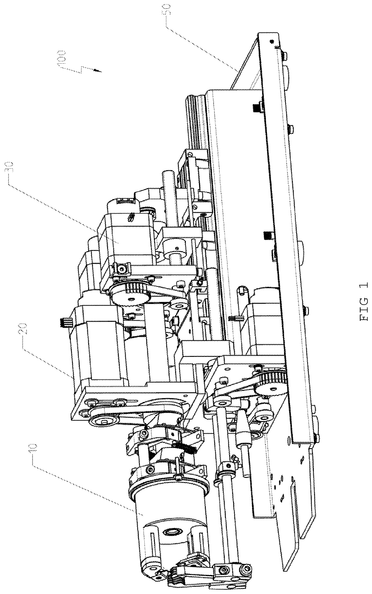
[0099]FIG. 1 shows a perspective view of a rotational insulation stripping machine 100. The insulation stripping machine 100 comprises an insulation-stripping head 10 with blades 2ra and 2rb arranged thereon (see FIG. 2), drive means 20 for the insulation-stripping head 10 and drive means 30 for the blades of the insulation-stripping head 10. The insulation stripping machine 100 has a frame 50, on which the components are mounted. The insulation stripping machine 100 comprises a device for detecting the contact of an electrical conductor by at least one electrically conductive tool 2ra, 2rb (see FIG. 2), also called blade-conductor contact.

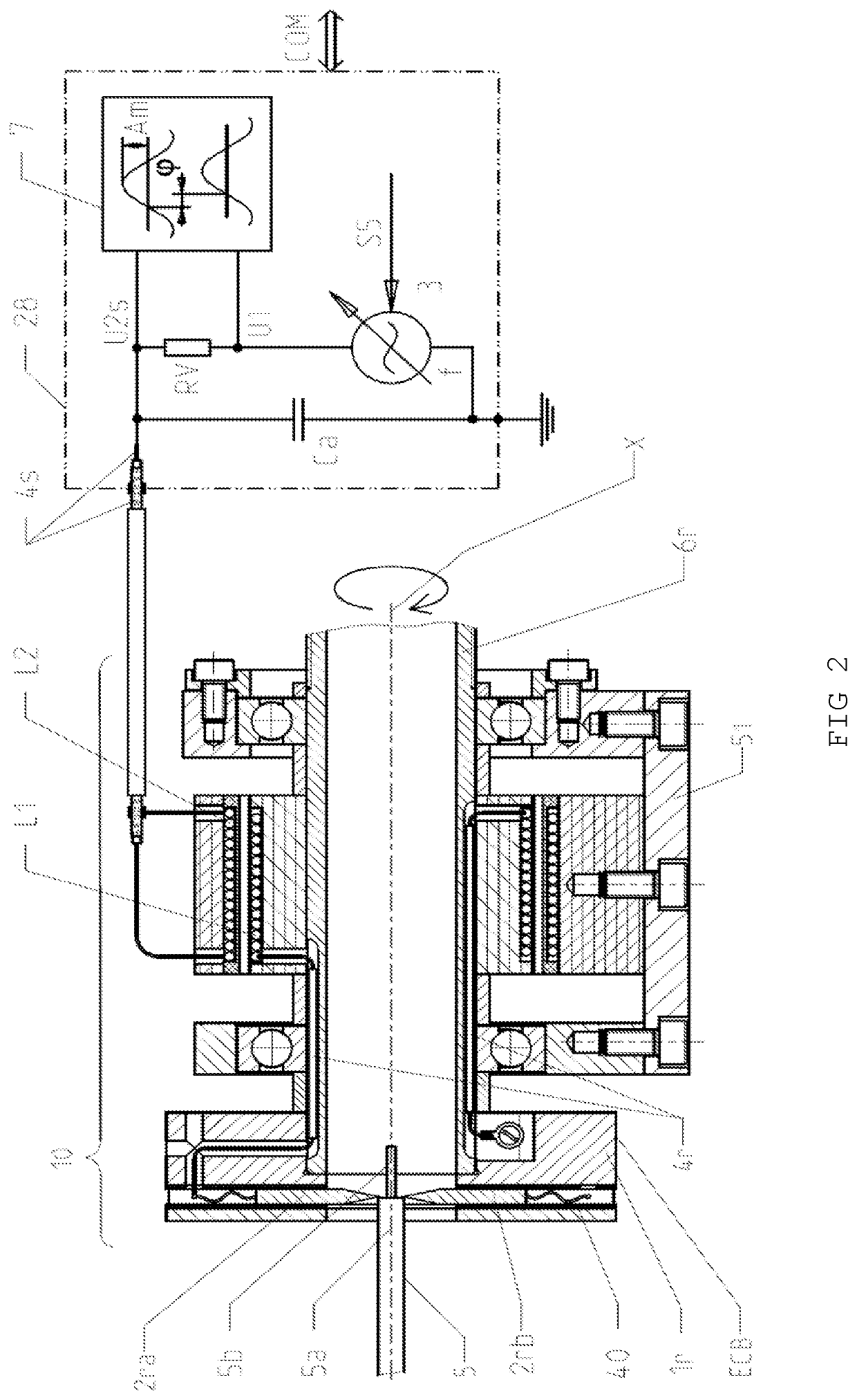
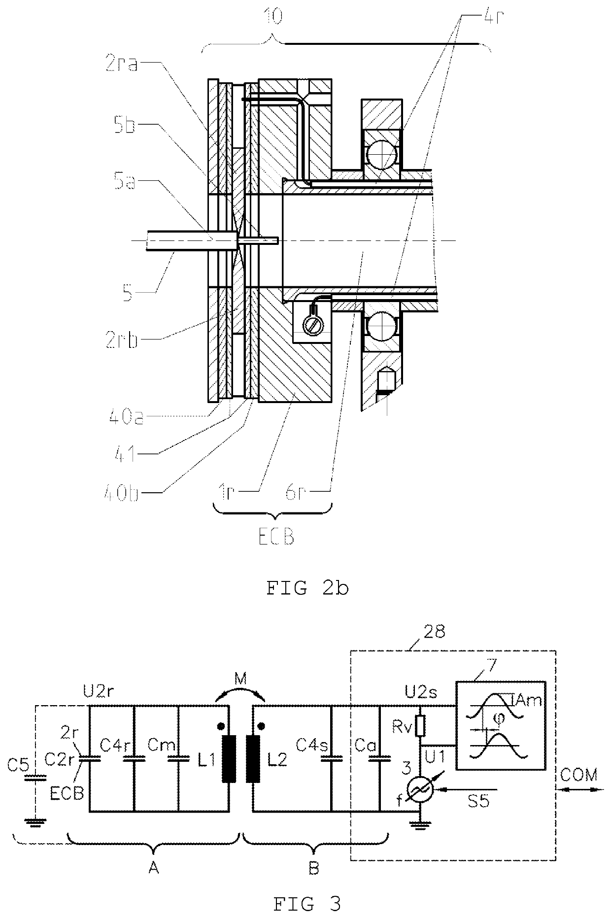
[0100]FIG. 2 is a schematic representation of a cross section along the rotation axis X of a rotational insulation stripping machine 100 (see FIG. 1). In the present case, the insulation-stripping head 10 is constructed as a hollow body and is connected to the hollow shaft 6r and mounted rotatably about the rotation axis X. In the left area of FIG...


PUM

PropertyMeasurementUnit
sickle cut angleaaaaaaaaaa
electrically conductiveaaaaaaaaaa
electrical insulationaaaaaaaaaa

Abstract

A device for identifying contact with an electrical conductor by at least one electrically conductive tool (2ra, 2rb). The device comprises a tool holder (Ir) rotationally mounted about a rotation axis (X), and the tool (2ra, 2rb) arranged on the tool holder. The device additionally comprises an electrically conductive body (ECB) and a rotor-side inductive element (L1) arranged on the electrically conductive body (Ir). A parallel resonant circuit comprises at least one rotor-side circuit element (A), at least one stator-side circuit element (B), a stationary circuit arrangement (28) and a stator-side inductive element (L2). The rotor-side inductive element and the stator-side inductive element are arranged to measure characteristic oscillation parameters (φ, Am, f) of the parallel resonant circuit independently of the rotation speed of the tool holder (Ir). An insulation-stripping machine and a method for identifying contact with an electrical conductor by at least one electrically conductive tool as disclosed.

Description

[0001]This application is a National Stage completion of PCT / IB2018 / 055117 filed Jul. 11, 2018.FIELD OF THE INVENTION[0002]The invention relates to a device for detecting contact with an electrical conductor by at least one electrically conductive tool, a method for identifying the contact with an electrical conductor by at least one electrically conductive tool, and an insulation stripping machine with at least one device for detecting the contact with an electrical conductor by at least one electrically conductive tool according to the independent claims.BACKGROUND OF THE INVENTION[0003]As the requirements regarding the quality of electrical cables have become increasingly strict, for the automobile or aviation industry for example, more and more often the slightest damage to the conductor such as scratches or scoring are considered to pose a risk, since damage of this kind together with the effects of vibration and / or corrosion can result in the conductor breaking. Accordingly, s...

Claims


Application Information

Patent Timeline
Patent Type & Authority Patents(United States)
IPC IPC(8): H01R43/05H02G1/12G01N27/02
CPCH02G1/1265G01N27/028H02G1/1248H02G1/1253H01H1/0015
Inventor BERGER, PATRICKDESCHLER, RAPHAELJOST, MICHAEL
Owner SCHLEUNIGER
Learn More