Binocular retinal imaging device, system, and method for tracking fixational eye motion

a retinal imaging and binocular technology, applied in the field of binocular retinal imaging devices, systems and methods for tracking fixational eye motion, can solve the problem that the fixational eye motion of the left and right eyes may not always be in syn

Active Publication Date: 2021-12-14
C LIGHT TECH INC
View PDF5 Cites 2 Cited by
  • Summary
  • Abstract
  • Description
  • Claims
  • Application Information

AI Technical Summary

Benefits of technology

[0008]The portability of the binocular system may assist a medical professional with the administration of a diagnostic test and / or the recording of fixational eye motion shortly after a patient experiences a possible brain injury. When the binocular system (or a portion thereof) is portable, the portable portion may be powered by an onboard battery and / or electrical power cord.

Problems solved by technology

However, in subjects with neurological and neurodegenerative conditions / diseases, the fixational eye motion of the left and right eyes may not always be in sync.

Method used


Image

  • Binocular retinal imaging device, system, and method for tracking fixational eye motion
  • Binocular retinal imaging device, system, and method for tracking fixational eye motion
  • Binocular retinal imaging device, system, and method for tracking fixational eye motion

Examples


Embodiment Construction

[0020]In the following detailed description of the preferred embodiments, reference is made to the accompanying drawings that form a part hereof, and in which are shown by way of illustration specific embodiments in which the invention may be practiced. It is understood that other embodiments may be utilized and structural changes may be made without departing from the scope of the present invention. Descriptions associated with any one of the figures may be applied to different figures containing like or similar components / steps. While the sequence diagrams each present a series of steps in a certain order, the order of some of the steps may be changed.

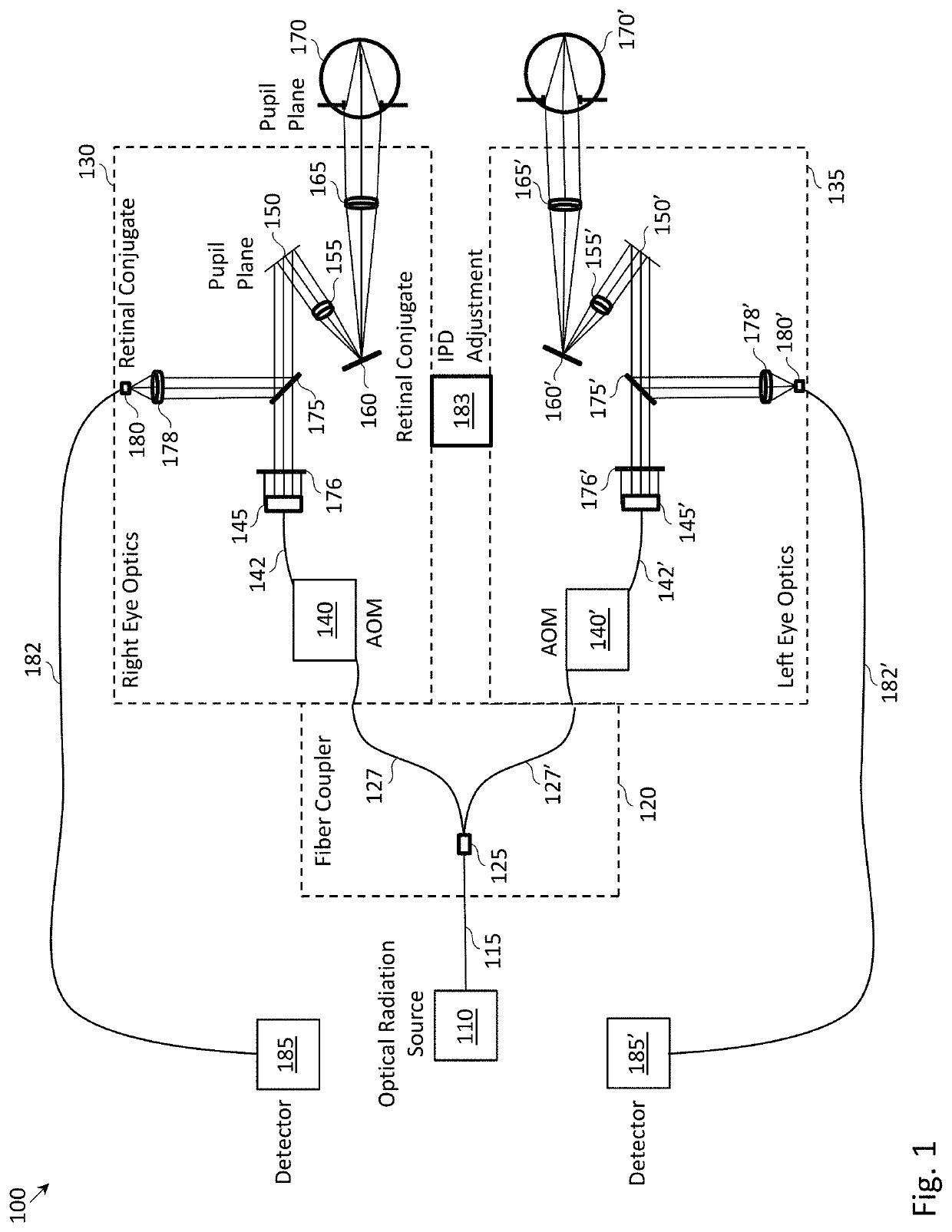
[0021]FIG. 1 depicts an example embodiment of binocular scanning laser ophthalmoscope (SLO) 100. In some instances, binocular SLO 100 may be instantiated as a hand-held device and in other instances, binocular system 100 may be embodied in a more permanent installation (e.g., in a doctor's or athletic trainer's office utilizing, for ...


PUM


Abstract

A binocular scanning laser ophthalmoscope (SLO) is used to track the fixational eye movement of each of the eyes of a subject. The binocular SLO may include right eye optics for imaging a portion of the retina of the right eye and left eye optics for imaging a portion of the retina of the left eye. Shifts in the imaged portion of the retina with respect to a reference image of the retina may be used to measure and track eye movement. The right eye optics and left eye optics may be separate imaging paths, each with its own bi-directional MEMS scanning mirror and Keplerian telescope. The use of the MEMS scanning mirrors minimizes the size and weight of the binocular SLO.

Description

RELATED APPLICATIONS[0001]This application is a non-provisional patent application of and claims priority to U.S. Provisional Application No. 62 / 433,952, filed Dec. 14, 2016, and U.S. Provisional Application No. 62 / 501,480, filed May 4, 2017.FIELD OF THE INVENTION[0002]The present invention relates to methods and systems for tracking fixational eye motion, and more particularly relates to simultaneously tracking the fixational eye motion of both eyes of a subject and / or comparing deviations between the fixational eye motion of the left and right eyes in order to determine or assess neurological diseases and / or disorders.BACKGROUND[0003]When a subject fixates upon a stationary reference point, the eyes of the subject are typically not stationary, but rather exhibit small jerk-like, involuntary motions known as microsaccades. Such motion, as well as other forms of motion that occur when the eyes of a subject are fixated upon a stationary reference point, may be referred to herein as “...

Claims


Application Information

Patent Timeline
Patent Type & Authority Patents(United States)
IPC IPC(8): A61B3/13A61B3/00A61B3/10A61B3/113G02B27/09G02B27/14G02B27/30
CPCA61B3/132A61B3/0008A61B3/1025A61B3/113G02B27/0994G02B27/14G02B27/30A61B3/08A61B3/11
Inventor SHEEHY, CHRISTYHELFT, ZACHARYNORTON, ANDREWPAGE, TAYLORSIMONSEN, MICHAELNI, YUN HUI
Owner C LIGHT TECH INC
Why Eureka
Try Eureka