Scanning laser ophthalmoscope for real-time eye tracking and method of operating same

a laser ophthalmoscope and real-time eye tracking technology, applied in the field of scanning laser ophthalmoscope for real-time eye tracking and a method for operating same, can solve the problems of system, like other similar systems in the conventional art, being limited to a 5-degree field of view, and no longer overlap

Active Publication Date: 2017-11-30
RGT UNIV OF CALIFORNIA
View PDF1 Cites 2 Cited by
  • Summary
  • Abstract
  • Description
  • Claims
  • Application Information

AI Technical Summary

Benefits of technology

[0009]A method of operating a scanning laser ophthalmoscope is disclosed. The scanning laser ophthalmoscope comprises a reflective optical system, an x- and y-coordinate scanner, and a refractive lens, the reflective optical system configured to direct light emitted from the light source through the refractive lens to a user's eye, and to direct light reflected from the user's eye through the refractive lens to the x- and y-coordinate The method comprises obtaining a first reference frame using the scanning laser ophthalmoscope, the first reference frame having a first field of view, the first reference frame including a first number of scanned lines and a first line separation between the scanned lines, obtaining a second frame using the scanning laser ophthalmoscope, the second frame including a second number of scanned lines smaller than the first number of scanned lines and a second line separation between the scanned lines equal to the first line separation, dividing the second frame into a plurality of strips, determining a second linearly stabilized frame by linearly cross-correlating each of the plurality of strips with the first reference frame, and determining a plurality of linear displacement values, each of the plurality of linear displacement values associated with a positional difference between one of the plurality of strips and the first reference frame.

Problems solved by technology

This system, like other similar systems in the conventional art, is however limited to a 5-degree field of view.
Moreover, this system is not suited for certain applications requiring the tracking of large eye movements or rapid eye movements.
One of the problems with choosing a single reference frame for eye tracking in this manner is that, when the eye moves perpendicular to the orientation of the strips that are used for eye tracking in the image, the new regions of the retina that are imaged may no longer overlap with the reference frame.
This can lead to a non-uniformly sampled eye motion trace.
Frame rates and image quality can also be limited when imaging or testing.
Current systems do not offer much flexibility in terms of stimulus wavelength composition and are unable to measure and account for imprecision introduced by the chromatic aberration of the eye.
Conventional mfERG devices have a spatial resolution much coarser than the scale of many disease-induced retinal abnormalities, such as retinal drusen, and are thus unable to fully characterize their functional implications.
The spatial resolution of mfERG is primarily limited by low signal-to-noise ratios.
However, protracted recording sessions with finer-grained stimuli have conventionally only yielded sensible data in cases where fixation was exceptionally stable, often in young and healthy subjects.

Method used


Image

  • Scanning laser ophthalmoscope for real-time eye tracking and method of operating same
  • Scanning laser ophthalmoscope for real-time eye tracking and method of operating same
  • Scanning laser ophthalmoscope for real-time eye tracking and method of operating same

Examples


Embodiment Construction

[0013]Sheehy et al., High-speed, image-based eye tracking with a scanning laser ophthalmoscope, Biomedical Optics Express, Sep. 19, 2012 is hereby incorporated by reference for its description of scanning laser ophthalmoscopes and methods of operating scanning laser ophthalmoscopes.

[0014]U.S. Pat. No. 6,890,076 B2 to Austin Roorda is hereby incorporated by reference for its description of scanning laser ophthalmoscopes and methods of operating scanning laser ophthalmoscopes.

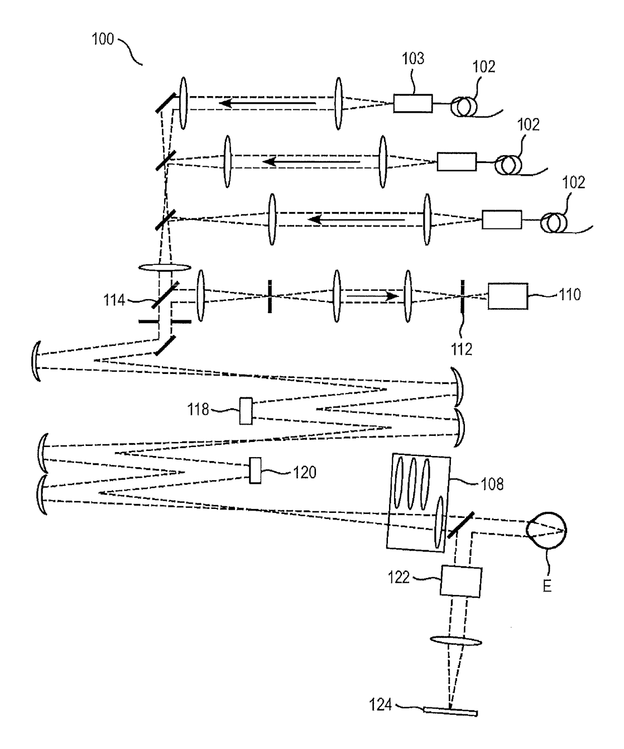
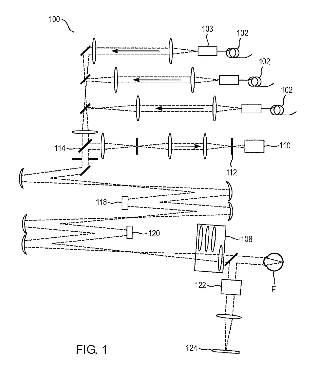
[0015]FIG. 1 shows exemplary embodiments of a scanning laser ophthalmoscope 100. The scanning laser ophthalmoscope 100 includes a light source 102, a reflective optical system 104, an x- and y-coordinate scanner 106, and a refractive lens 108. The reflective optical system 104 is configured to direct light emitted from the light source 102 through the refractive lens 108 to a user's eye E, and to direct light reflected from the user's eye E through the refractive lens 108 to the x- and y-coordinate scanner 106. A...


PUM


Abstract

A scanning laser ophthalmoscope and a method of operating a scanning laser ophthalmoscope are disclosed. The scanning laser ophthalmoscope includes a light source, a reflective optical system, an x- and y-coordinate scanner, and a refractive lens. The reflective optical system is configured to direct light emitted from the light source through the refractive lens to a user's eye, and to direct light reflected from the user's eye through the refractive lens to the x- and y-coordinate scanner.

Description

CROSS-REFERENCE TO RELATED APPLICATION[0001]This application is a non-provisional application claiming the benefits of U.S. Provisional Patent Application Ser. No. 62 / 077,022 filed on Nov. 7, 2014, the content of which is hereby incorporated by reference.FIELD[0002]The present disclosure relates to a scanning laser ophthalmoscope for real-time eye tracking and a method for operating a scanning laser ophthalmoscope for real-time eye tracking.BACKGROUND INFORMATION[0003]Conventional scanning laser ophthalmoscopes provide structural imaging and real-time eye tracking and targeted stimulus delivery. For examples, Sheehy et al., High-speed, image-based eye tracking with a scanning laser ophthalmoscope, Biomedical Optics Express, Sep. 19, 2012, describes a confocal scanning laser ophthalmoscope. This scanning laser ophthalmoscope includes a light source, a reflective mirror assembly, and an x- and y-coordinate scanner. In one optical design described in this publication, light exiting a s...

Claims


Application Information

Patent Timeline
Patent Type & Authority Applications(United States)
IPC IPC(8): A61B3/10A61B3/113A61B3/12
CPCA61B3/1025A61B3/12A61B3/102A61B3/113
Inventor ROORDA, AUSTIN J.SHEEHY, CHRISTY K.TIRUVEEDHULA, PAVANTUTEN, WILLIAM
Owner RGT UNIV OF CALIFORNIA
Why Eureka
Try Eureka