Electrostatic comb actuator, deformable mirror using the electrostatic comb actuator, adaptive optics system using the deformable mirror, and scanning laser ophthalmoscope using the adaptive optics system

a comb actuator and electrostatic technology, applied in the direction of generator/motor, optical radiation measurement, instruments, etc., can solve the problems of reduced connection strength, reduced connection strength, and thinned comb electrodes, etc., to achieve the effect of increasing the connection strength

Inactive Publication Date: 2014-05-15
CANON KK
View PDF2 Cites 2 Cited by
  • Summary
  • Abstract
  • Description
  • Claims
  • Application Information

AI Technical Summary

Benefits of technology

[0007]The present invention has been made in order to solve the above-mentioned problem, and has an object to provide, for example, an electrostatic comb actuator capable of increasing a displacement amount of a movable portion in a direction perpendicular to a substrate, and increasing the strength of a connection portion in a separation groove for electrodes.

Problems solved by technology

However, in this case, when the beam is thinned, the comb electrodes are also thinned.
As a result, sufficient displacement amount may not be obtained.
However, considering the above-mentioned configuration, thinning the beam results in reduction in strength of the connection portion.

Method used


Image

  • Electrostatic comb actuator, deformable mirror using the electrostatic comb actuator, adaptive optics system using the deformable mirror, and scanning laser ophthalmoscope using the adaptive optics system
  • Electrostatic comb actuator, deformable mirror using the electrostatic comb actuator, adaptive optics system using the deformable mirror, and scanning laser ophthalmoscope using the adaptive optics system
  • Electrostatic comb actuator, deformable mirror using the electrostatic comb actuator, adaptive optics system using the deformable mirror, and scanning laser ophthalmoscope using the adaptive optics system

Examples


example 1

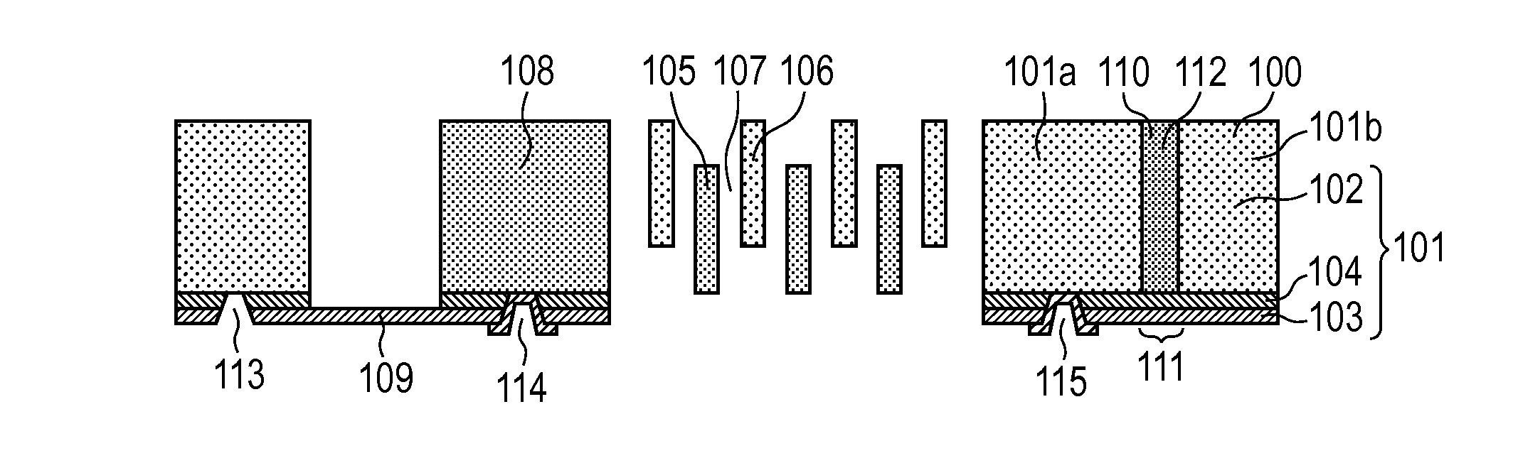
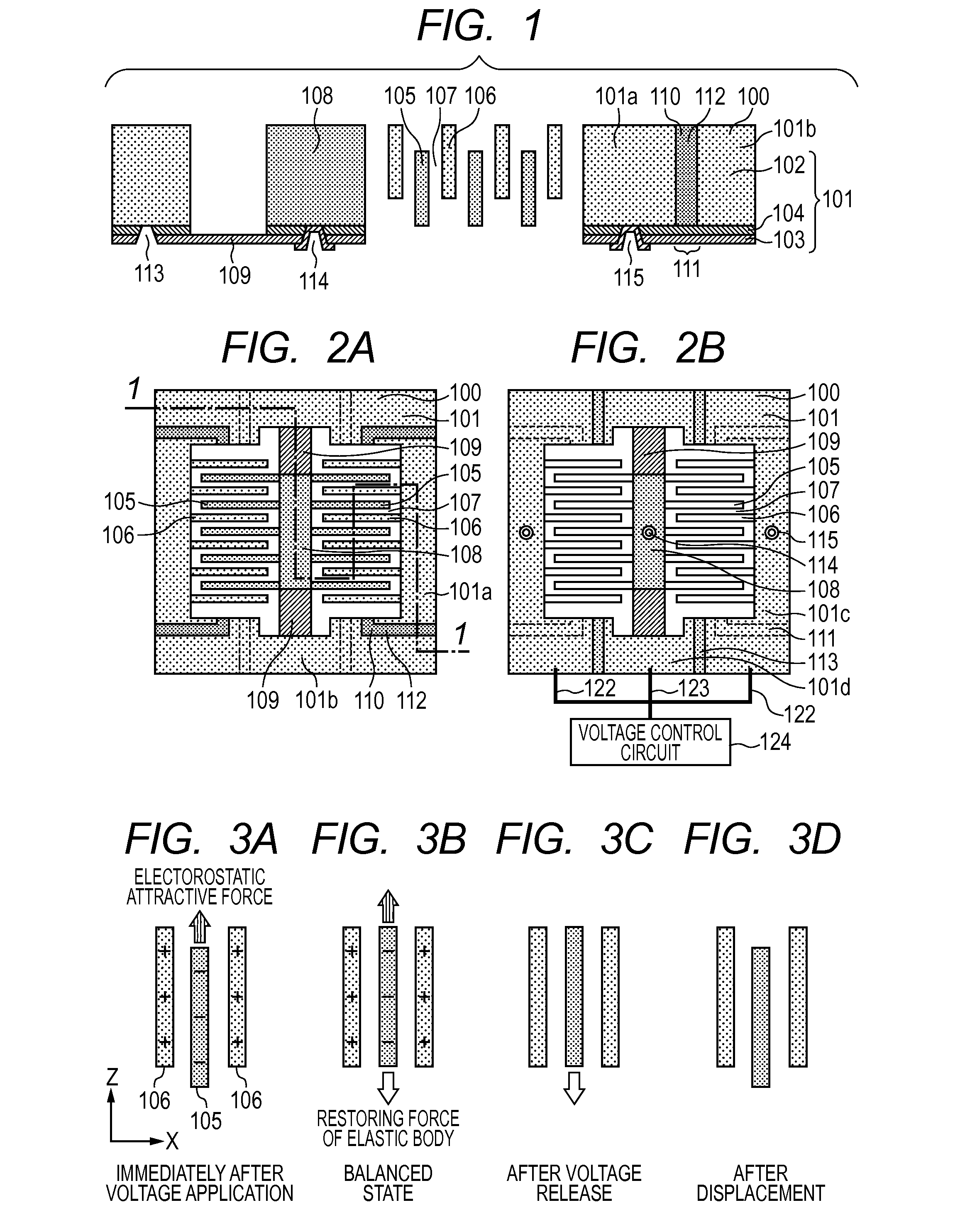
[0032]With reference to FIG. 1, an electrostatic comb actuator according to Example 1 of the present invention is described. The actuator according to Example 1 includes a reinforcing member made up of the insulating layer 104 and the insulating material 112 filled in the handle layer separation groove 110. The substrate 101 in which the electrostatic comb actuator 100 is formed is an SOI substrate including the handle layer 102, the device layer corresponding to the elastic body layer 103, and the insulating layer (BOX layer) 104 sandwiched therebetween. The handle layer of the substrate 101 is made of, for example, p-type monocrystalline silicon having a crystal plane orientation of (100), and has a thickness of, for example, 200 μm and a resistivity of, for example, 0.01 Ωcm to 0.02 Ωcm. The device layer of the substrate 101 is made of, for example, p-type monocrystalline silicon having a crystal plane orientation of (100), and has a thickness of 1 μm and a resistivity of 0.01 Ωc...

example 2

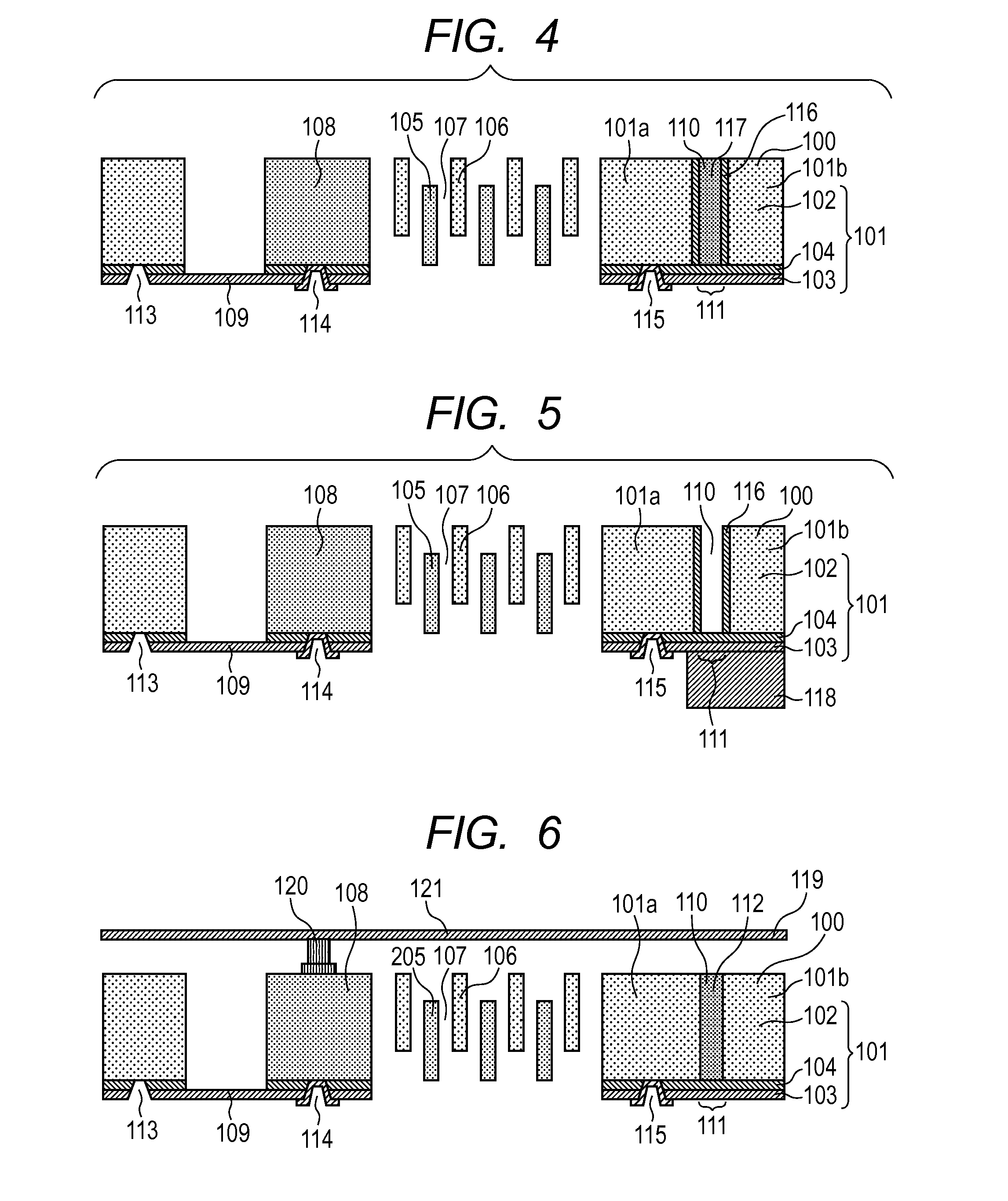
[0036]FIG. 4 is a sectional view illustrating an electrostatic comb actuator according to Example 2 of the present invention. The actuator according to this example is different from the configuration of Example 1 in that the handle layer separation groove 110 has an insulating film 116 formed on a side wall thereof, and an insulating material filled in the handle layer separation groove 110 as the structure reinforcing portion is a resin material 117. The substrate 101 is made up of an SOI substrate having the same configuration as that of Example 1.

[0037]On the side wall of the handle layer separation groove 110, as the insulating film 116, for example, a silicon thermally-oxidized film is formed so as to have a thickness of, for example, 1 μm. With the insulating film 116, the electrical separation is more reliably achieved between the handle layer 101a connected to the fixed comb electrode 106 and the handle layer 101b connected to the elastic body 109 supporting the movable com...

example 3

[0041]FIG. 5 is a sectional view illustrating an electrostatic comb actuator according to Example 3 of the present invention. The actuator according to this example is different from the configuration of Example 2 in that the actuator according to this example includes, as the structure reinforcing portion, a member formed across the handle layer separation groove 110 and in contact with the elastic body layer 103 on the opposite side to the handle layer 101a, and does not include a material filled in the handle layer separation groove 110. The substrate 101 is made up of an SOI substrate having the same configuration as that of Example 1.

[0042]The structure reinforcing portion includes, in order to increase the strength of the connection portion 111 even when the elastic body layer 103 is thin, a base member 118 including an insulating material layer formed across the handle layer separation groove 110 and in contact with the device layer 103 on the opposite side to the handle laye...


PUM


Abstract

Provided is an actuator formed in a substrate including a handle layer, an elastic body layer, and an insulating layer, the actuator including a movable portion supported to a support portion by an elastic body, a movable comb electrode formed on the movable portion, a fixed comb electrode supported by the support portion, and electrode wirings connected to the respective comb electrodes in which the elastic body supports the movable portion such that the movable portion is displaceable in a direction perpendicular to the substrate in accordance with voltages applied to the comb electrodes; the comb electrodes are made up of the handle layer, and the elastic body is made up of the elastic body layer; and a handle layer separation groove is provided to electrically separate between the handle layers of the support portions supporting the comb electrodes, and a structure reinforcing portion is formed across the separation groove.

Description

BACKGROUND OF THE INVENTION[0001]1. Field of the Invention[0002]The present invention relates to an electrostatic comb actuator in a MEMS field or the like, and more particularly, to an electrostatic comb actuator that is applicable to, for example, a deformable mirror. Moreover, the present invention relates to an adaptive optics system using the deformable mirror, and a scanning laser ophthalmoscope using the adaptive optics system.[0003]2. Description of the Related Art[0004]An electrostatic comb actuator is one of drive units having a fine mechanical structure, and can perform micro-driving in accordance with a potential difference between comb electrodes. Further, the electrostatic comb actuator is also applicable to sensing by measuring the change in distance between comb teeth, which is caused by external factors, as a change in electrostatic capacitance. The electrostatic comb actuator can thus be used as a micro-driving unit and a sensor structure, and hence is expected to ...

Claims


Application Information

Patent Timeline
Patent Type & Authority Applications(United States)
IPC IPC(8): H02N1/00A61B3/12G02B26/08
CPCH02N1/006G02B26/0825A61B3/12G02B26/0841A61B3/1025A61B3/1225H02N1/002H02N1/008
Inventor TAMAMORI, KENJIOZAKI, HIROYUKI
Owner CANON KK
Why Eureka
Try Eureka