Improvements in and related to ophthalmoscopy

An ophthalmoscope and eye technology, applied in the field of deviation correction, can solve the problems of retinal spatial information loss fidelity, low fidelity, unsatisfactory image quality, etc.

Active Publication Date: 2018-05-01
OPTOS PLC
View PDF5 Cites 0 Cited by
  • Summary
  • Abstract
  • Description
  • Claims
  • Application Information

AI Technical Summary

Problems solved by technology

As a result, retinal spatial information may be lost or recorded with a lower fidelity than theoretically possible
In particular, blurring and darkening can be seen at the edges of the image produced by the ophthalmoscope, making the image quality even more unsatisfactory

Method used


Image

  • Improvements in and related to ophthalmoscopy
  • Improvements in and related to ophthalmoscopy
  • Improvements in and related to ophthalmoscopy

Examples


Embodiment Construction

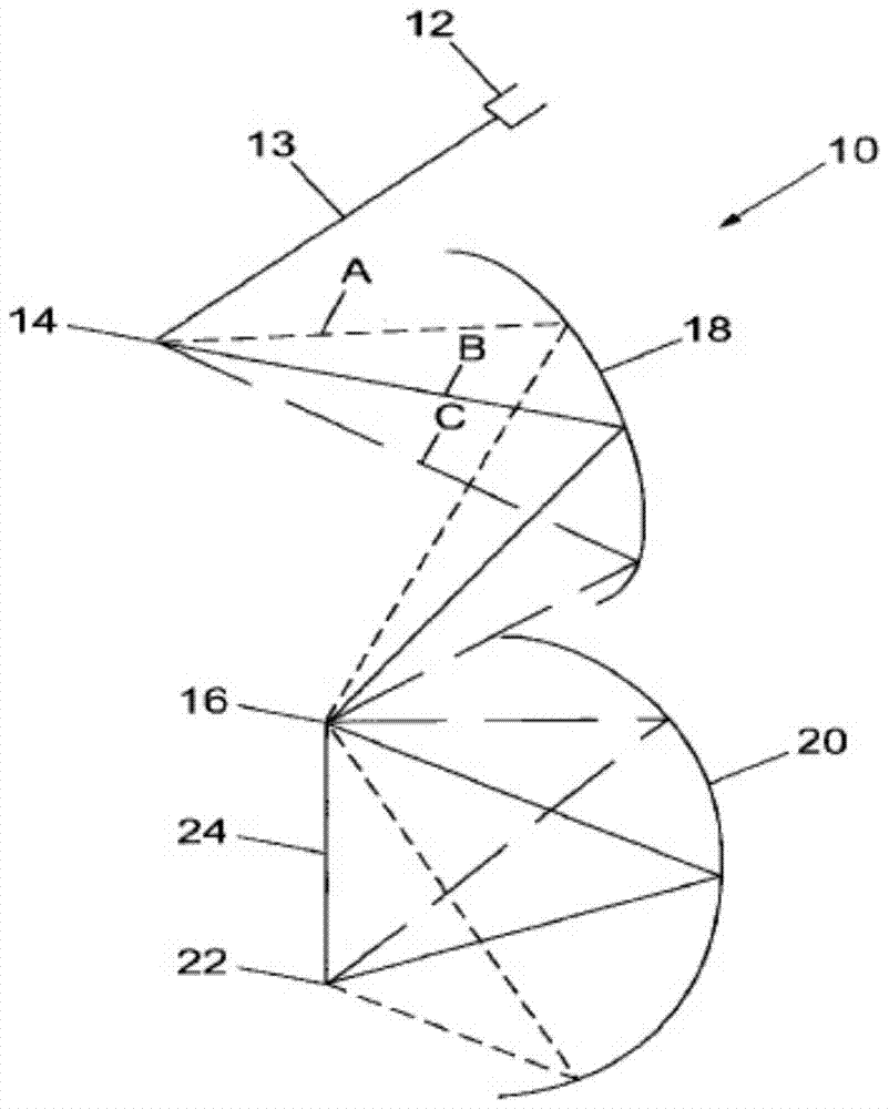
[0038] see figure 1 The ophthalmoscope 10 includes a light source 12 emitting a light beam 13, scan relay elements (including a first scan element 14, a second scan element 16, a scan compensation element 18 and a scan transfer element 20). The first scanning element 14 comprises a rotating polygonal mirror and the second scanning element 16 comprises an oscillating plane mirror. The scan compensation element 18 comprises an ellipsoidal mirror and the scan transfer element 20 comprises an aspherical mirror. The ophthalmoscope 10 also includes aberration correction elements (not shown).

[0039] A light source 12 directs an incident light beam 13 to a first scanning element 14 . This produces a beam scan in the first vertical dimension (shown as rays A, B and C). The incident light beam impinges on the scan compensation element 18 and is reflected therefrom to the second scan element 16 . This produces a scan of the incident beam in the second horizontal dimension. The inc...


PUM


Abstract

A scanning laser ophthalmoscope for scanning the retina of an eye is provided, comprising: a light source emitting a beam of light, a scanning relay element, wherein the light source and the scanning relay element provide for transmission from a surface point source at the pupil point of the eye to the eye Two-dimensional scanning of the light beam of the retina, and a static aberration correcting element (30), wherein the static aberration correcting element is shaped to provide correction for the aberration of at least some of the scan relay elements, the static aberration correcting element in the ophthalmoscope The position of is chosen to provide correction for the misalignment of at least some of the scan relay elements, which maintains the transfer of the light beam from the surface point source at the pupil point of the eye to the retina of the eye. The invention also provides a deflection correction element and a method of determining the shape of the deflection correction element.

Description

technical field [0001] The present invention relates to improvements in and relating to ophthalmoscopes, in particular to corrections for aberrations in images introduced by ophthalmoscope systems. Background technique [0002] An ophthalmoscope typically includes a system for directing light from a light source to a portion of the subject's retina aligned with the object plane of the ophthalmoscope, and for collecting light reflected from the portion of the subject's retina in a detector. Collectively, a number of optical elements and scanning elements (collectively referred to as scan relay elements) are used to direct and collect light, and the collected light is used to form an image of the portion of the subject's retina. Due to the optical properties of the scan relay elements, especially in relation to wide field scan relay elements, deviations can occur in ophthalmoscope systems. For this reason, retinal spatial information may be lost or recorded with a lower fidel...

Claims


Application Information

Patent Timeline
Patent Type & Authority Patents(China)
IPC IPC(8): A61B3/12
CPCG02B27/0025G02B27/0087G02B27/0031A61B3/1025A61B3/1225
Inventor G·穆约D·斯旺
Owner OPTOS PLC
Why Eureka
Try Eureka