Scanning laser ophthalmoscope

a laser ophthalmoscope and scanning laser technology, applied in the field of scanning laser ophthalmoscopes, can solve the problems of affecting the appearance affecting the diagnosis of the affected area, so as to achieve the effect of diagnosis

Inactive Publication Date: 2010-09-14
NIDEK CO LTD
View PDF11 Cites 2 Cited by
  • Summary
  • Abstract
  • Description
  • Claims
  • Application Information

AI Technical Summary

Benefits of technology

[0006]It is an object of the present invention to provide a scanning laser ophthalmoscope that can obtain a fundus image effective in diagnosis and, more particularly to, a scanning laser ophthalmoscope that can make a fundus site clear which is observed by a monitor in fluorescent fundus photography (angiography).

Problems solved by technology

However, according to fluorescent fundus photography (angiography), an image of the fundus is created in its fluorescent state and so liable to be fainted (blurred).
For example, if a fluorescent agent partially leaks out of the blood vessels of the fundus in FAG, the part looks (is displayed) blurred whitely, thus making it difficult to identify an affected area.
On the other hand, in ICG, the capillary vessels which are present in plenty under the retina pigment epithelium are in a strong fluorescent state, so that the image looks (is displayed) blurred whitely, thus making it difficult to identify an affected area.

Method used


Image

  • Scanning laser ophthalmoscope
  • Scanning laser ophthalmoscope
  • Scanning laser ophthalmoscope

Examples


Embodiment Construction

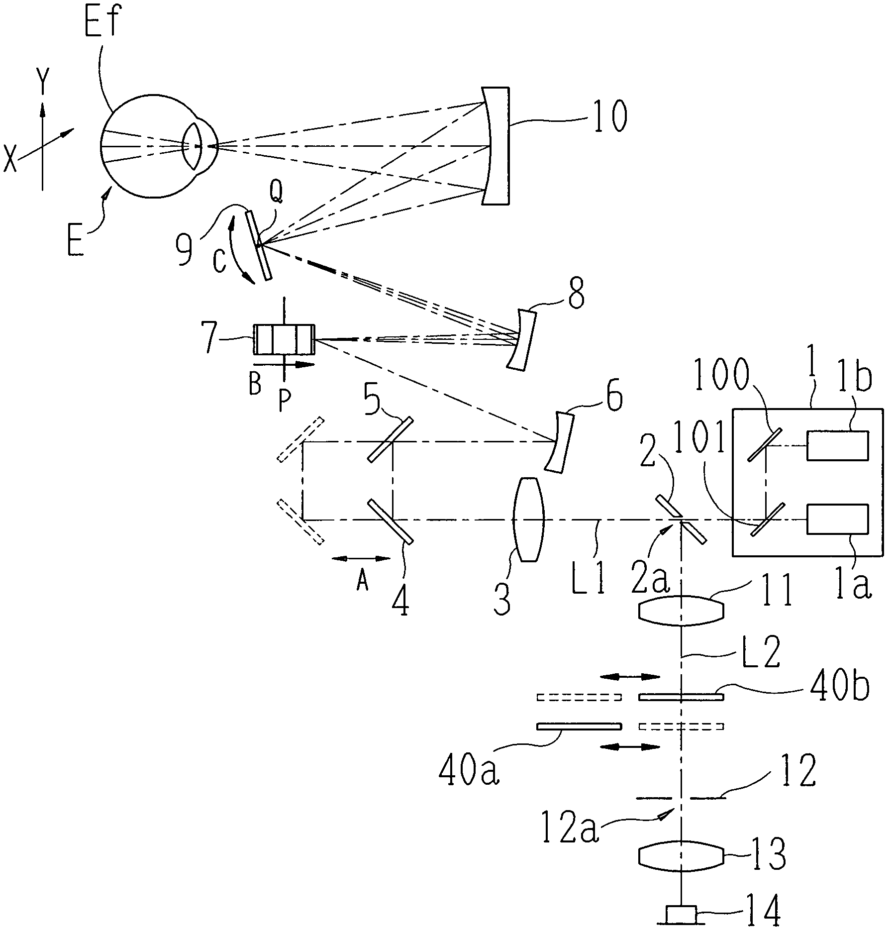
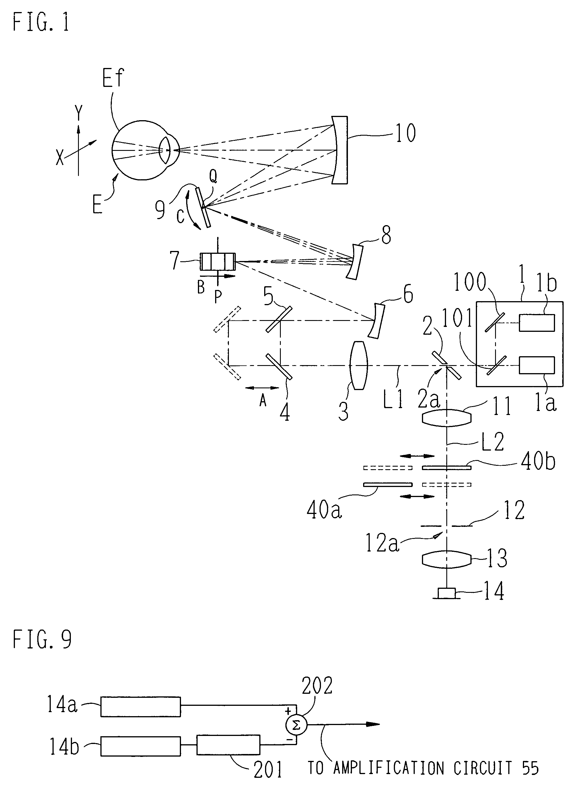
[0028]The following will describe an embodiment of the present invention with reference to the drawings. FIG. 1 shows an outlined configuration diagram of an optical system of a scanning laser ophthalmoscope in accordance with an embodiment of the present invention.

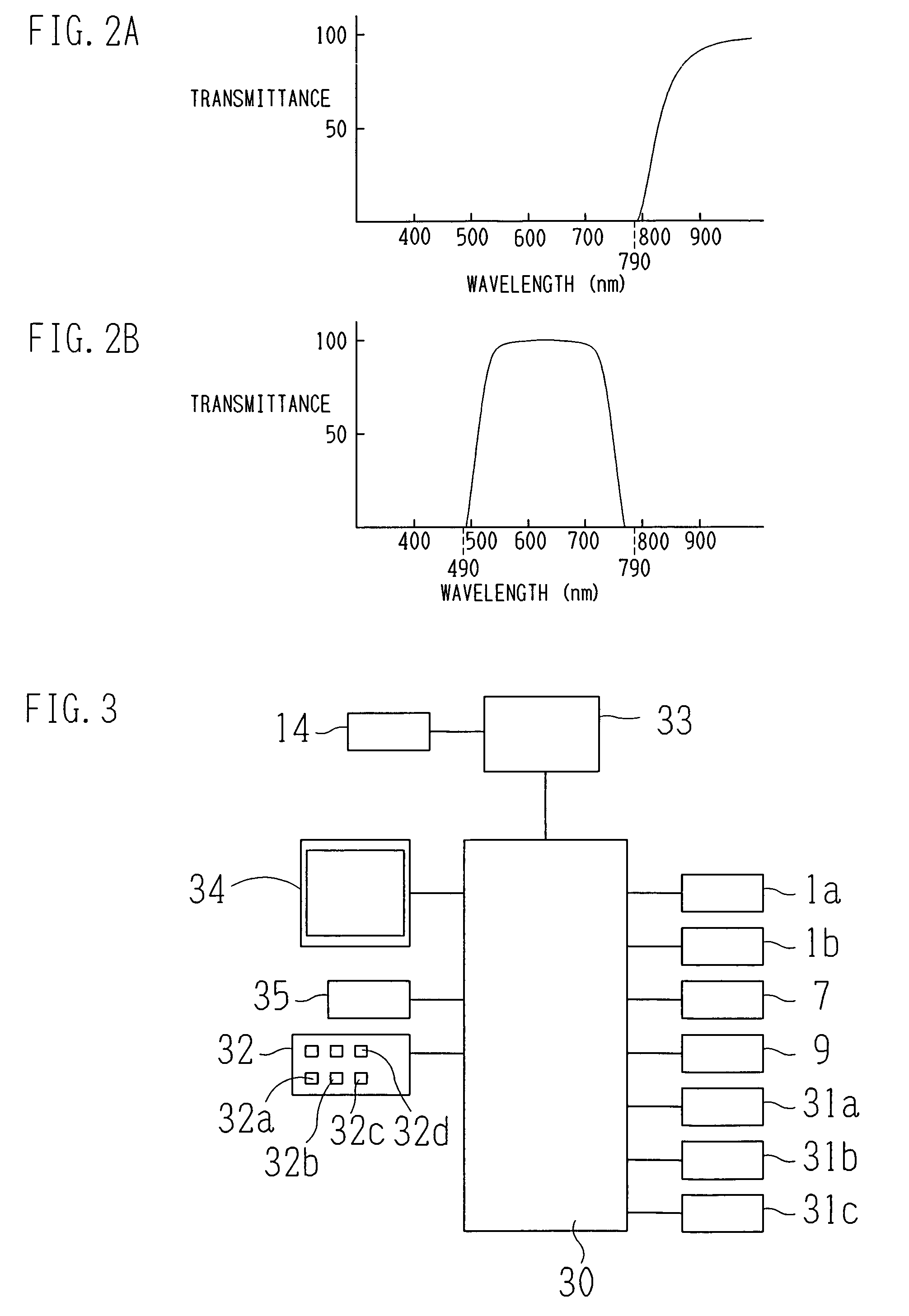
[0029]A beam emitting portion (beam emitter) 1 includes a first laser source 1a that emits a first laser beam having an infrared band wavelength, a second laser-source 1b that emits a laser beam having a visible band wavelength, a total reflection planar mirror 100, and a dichroic mirror 101 that transmits infrared light and reflects visible light. It is to be noted that in the present embodiment, the first laser source 1a emits a first laser beam having a wavelength in the vicinity of 790 nm and the second laser source 1b emits a second laser beam having a wavelength in the vicinity of 490 nm. The first beam emitted from the first laser source 1a passes through the dichroic mirror 101 and travels along an optical axis L1...


PUM


Abstract

A scanning laser ophthalmoscope comprises: a laser source that emits a laser beam; an irradiation optical system that scans the laser beam over a fundus two-dimensionally; a photoreceptor optical system that receives reflection from the fundus by using a photoreceptor element; an image processor that obtains an image of the fundus based on an output signal from the photoreceptor element; a monitor; and a controller that causes the monitor to display the obtained fundus image, wherein the image processor comprises a subtractive processing circuit that performs time-subtractive processing on the output signal from the photoreceptor element in a state where the output signal is input as an analog signal, and forms the fundus image based on the signal subjected to the subtractive processing.

Description

BACKGROUND OF THE INVENTION[0001]1. Field of the Invention[0002]The present invention relates to a scanning laser ophthalmoscope that obtains an image of the fundus of an examinee by scanning the fundus with a laser beam.[0003]2. Description of the Related Art[0004]A scanning laser ophthalmoscope is known that scans a laser beam two-dimensionally over the fundus of an examinee and receives reflection from the fundus, thereby obtaining an image of the fundus. According to such an apparatus, it is possible to irradiate a laser beam having predetermined wavelength characteristics as an excitation light onto the fundus of an examinee subjected to intravenous injection of a fluorescent agent and receive reflection from the fundus, thereby carrying out fluorescent fundus angiography (hereinafter abbreviated as FAG), indocyanine green fundus angiography (hereinafter abbreviated as ICG), etc.[0005]However, according to fluorescent fundus photography (angiography), an image of the fundus is ...

Claims


Application Information

Patent Timeline
Patent Type & Authority Patents(United States)
IPC IPC(8): A61B3/10
CPCA61B3/1025
Inventor FUJISHIRO, AKIHIROAKITA, JUNICHI
Owner NIDEK CO LTD
Why Eureka
Try Eureka