Scanning laser ophthalmoscopes

Pending Publication Date: 2021-06-03
OXFORD UNIV INNOVATION LTD
View PDF0 Cites 1 Cited by
  • Summary
  • Abstract
  • Description
  • Claims
  • Application Information

AI Technical Summary

Benefits of technology

[0017]Ophthalmoscopes according to the invention use a reflective, rather than refractive, design that carries additional benefits where broadband or multi-wavelength light sources are used and avoid back reflections that can affect image quality and wavefront sensor performance.
[0018]Ophthalmoscopes according to some embodiments of the invention can maintain a planar optical alignment without the build-up of astigmatism using compact, reconfigurable modules based on an Offner relay system. This design can result in a compact system tha

Problems solved by technology

Optical aberrations in the eye degrade the quality of the focused beam on the first pass and further degrade it as the light is reflected back out of the eye.
However, using spherical mirrors in this way introduces astigmatism into the wavefront and this accumulates with each reflection from a spherical mirror.
This system achieves diffraction-limited performanc

Method used


Image

  • Scanning laser ophthalmoscopes
  • Scanning laser ophthalmoscopes
  • Scanning laser ophthalmoscopes

Examples


Embodiment Construction

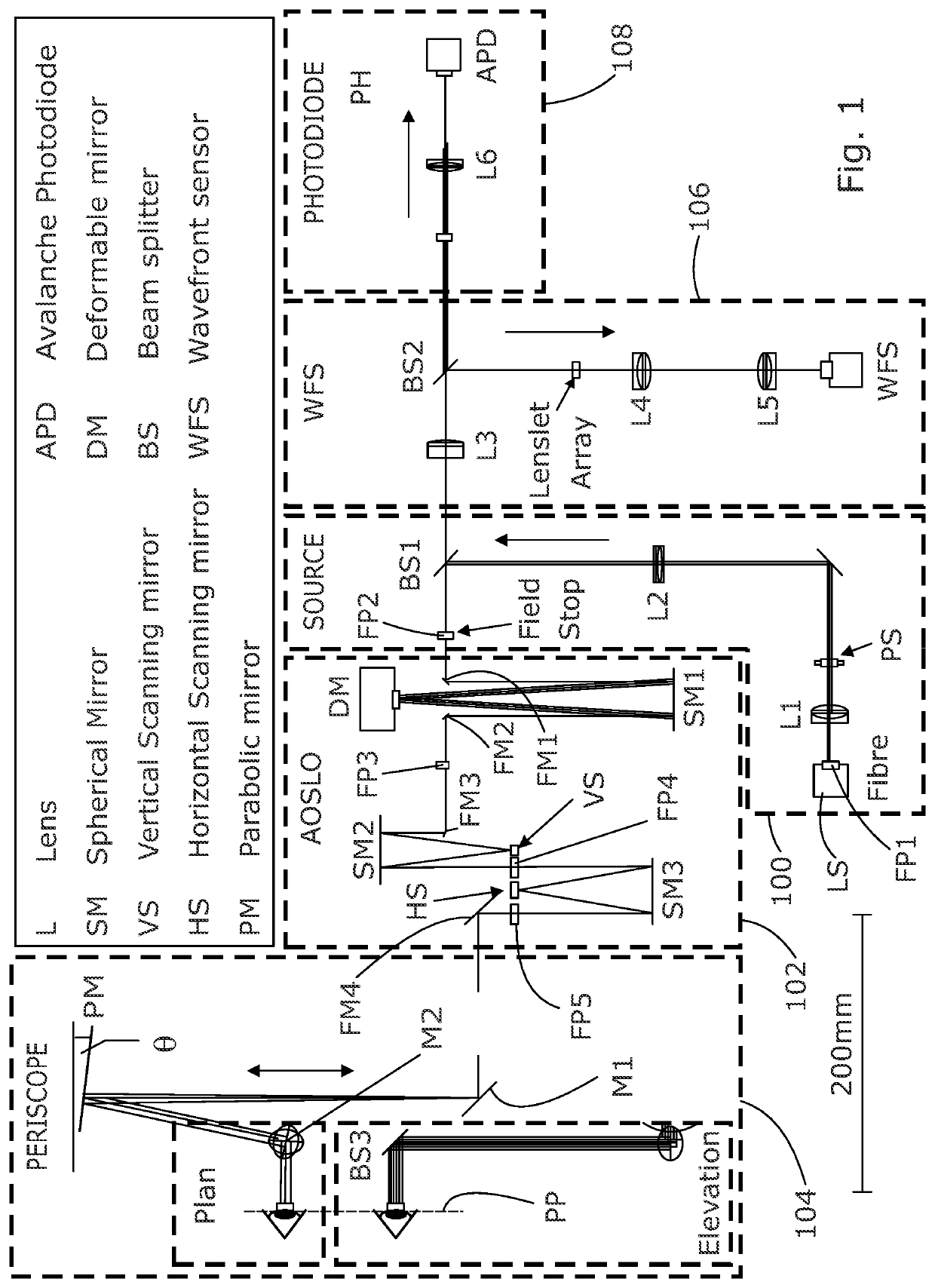
[0029]Referring to FIG. 1, the AOSLO comprises a number of components, which may conveniently be provided in a number of modules. For example, these may include a light source module 100, an AOSLO or adaptive optics scanning module 102, a periscope module 104, a wavefront sensing module 106 and a detector or photodiode module 108. The source module 100 relays the light beam from a superluminescent diode (fibre-fed) via reflection (e.g. 8% reflection) from a beam splitter BS1 to the AOSLO module 102, where the scanning and wavefront compensation takes place. The scanned, wavefront-compensated light is delivered to the eye of a subject via the periscope module 104, which defines a pupil plane PP where the pupil of the eye is to be located for inspection, and light returning from the eye passes back through the periscope and AOSLO modules 102. The beamsplitter BS1 in the source module 100 transmits a proportion (e.g. 92%) of the returned light into the next two modules 106, 108. A prop...


PUM


Abstract

A scanning laser ophthalmoscope comprises a light source (LS) arranged to generate a beam of light; a deformable mirror relay (DM, SM1); a first scanning relay (VS, SM2); a second scanning relay (HS, SM3); a wavefront sensor (WFS); and a detector (APD). The deformable mirror relay comprises a deformable flat mirror (DM) arranged to compensate for distortions detected by the wavefront sensor (WFS). Each of the scanning relays comprises a flat scanning mirror (VS, HS) arranged to scan the beam across the eye of a subject. At least one of the relays has an entry focal plane and an exit focal plane and further comprises a spherical mirror arranged to reflect the beam from the entry focal plane onto the flat mirror and to reflect light from the flat mirror into the exit focal plane.

Description

FIELD OF THE INVENTION[0001]The invention relates to scanning laser ophthalmoscopes and in particular to adaptive optics scanning laser ophthalmoscopes. It also has application in other systems that relay pupil conjugate planes, such as scanning confocal microscopes.BACKGROUND TO THE INVENTION[0002]A scanning laser ophthalmoscope (SLO) generally comprises a light source that generates a light beam, two scanners, which may use movable mirrors, to scan the beam in orthogonal directions across the part of the eye to be imaged, and a detector, such as a photodiode, to measure the reflected beam in order to generate image data.[0003]Optical aberrations in the eye degrade the quality of the focused beam on the first pass and further degrade it as the light is reflected back out of the eye. A confocal pinhole in the SLO acts to spatially filter the reflected light to improve the effective resolution, but with a reduction in the amount of light reaching the detector. A larger pinhole can be...

Claims


Application Information

Patent Timeline
IPC IPC(8): A61B3/10A61B3/14
CPCA61B3/1025A61B3/14
Inventor YOUNG, LAURAMORRIS, TIMOTHYSMITHSON, HANNAHSAUNTER, CHRISTOPHER
Owner OXFORD UNIV INNOVATION LTD
Why Eureka
Try Eureka