Valve device
a valve device and valve body technology, applied in the direction of fluid pressure control, process and machine control, instruments, etc., can solve the problems of large solenoid, complex structure of valve devices, and large power consumption, and achieve the effect of small operating force, simple configuration, and reduced air sucked into the pump
- Summary
- Abstract
- Description
- Claims
- Application Information
AI Technical Summary
Benefits of technology
Problems solved by technology
Method used
Image
Examples
first embodiment
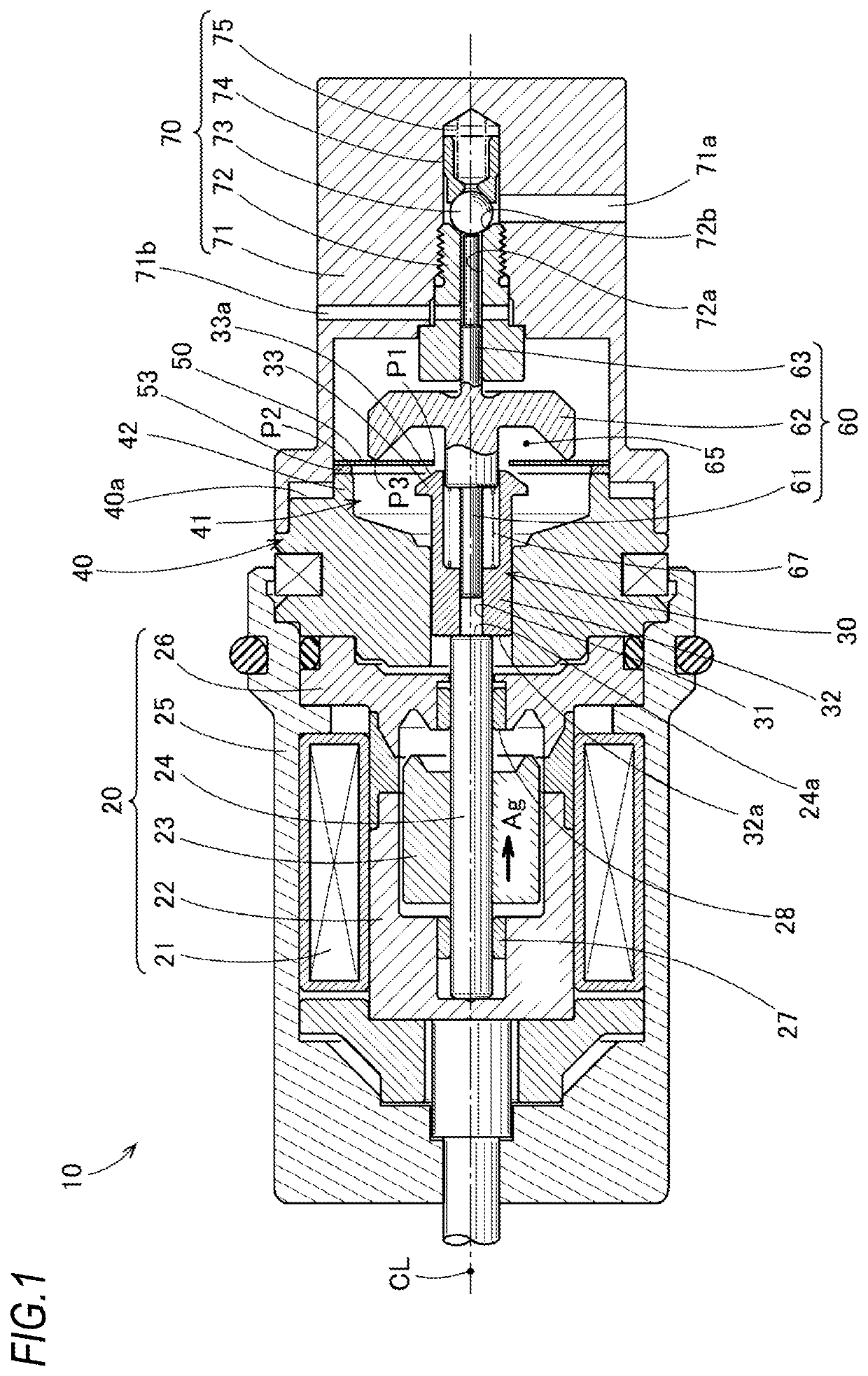
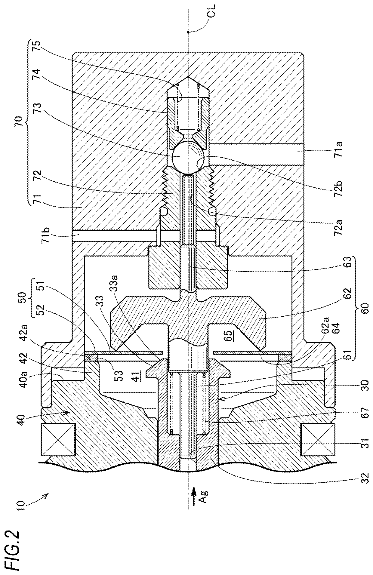
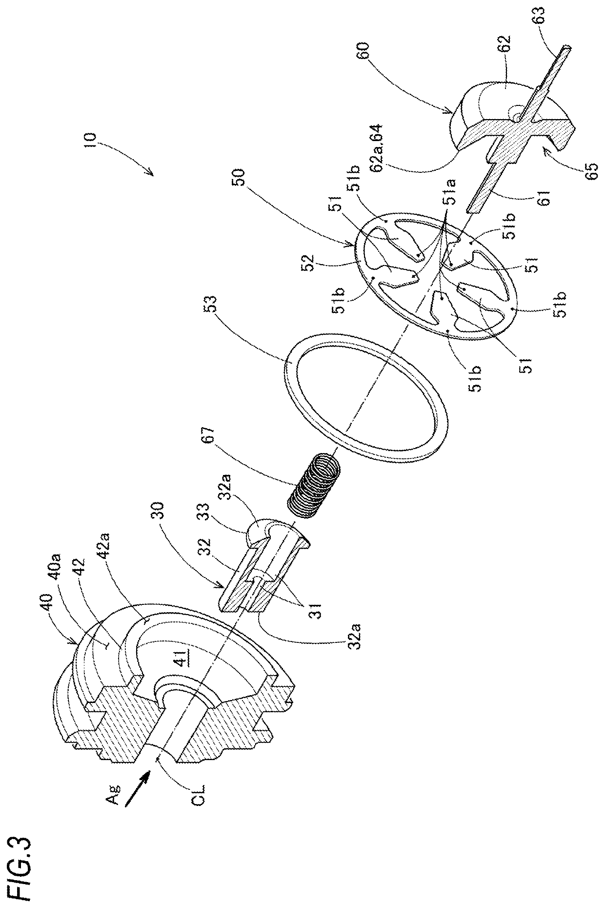
[0050]The valve device 10 according to a first embodiment will be described with reference to FIGS. 1 to 7. As depicted in FIG. 1, a valve device 10 is a coaxial direct acting valve that includes an operating unit 20, a first pushing member 30, a plate-like member 50, a second pushing member 60, and a valve 70 as main components.
[0051]It is preferable that the operating unit 20 is provided with an operating rod 24 capable of advancing and retracting (that is, sliding), and includes an electromagnetic solenoid. The electromagnetic solenoid 20 (operating unit 20) includes a push-type solenoid advancing a plunger 23 by exciting an exciting coil 21. Further, it is more preferable that the electromagnetic solenoid 20 is a so-called proportional solenoid in which the advancing distance of the plunger 23 is proportional to the current supplied to the exciting coil 21. With the configuration of the proportional solenoid, the opening degree of the valve 70 can be adjusted according to the ad...
second embodiment
[0105]FIG. 10 is an illustration correspondence to FIG. 1 described above, depicting a cross-sectional structure of the valve device 10A. FIG. 11 is an illustration corresponding to FIG. 2 described above. FIG. 12 is an illustration corresponding to FIG. 7 described above. In addition, FIG. 5 described above is used as it is.
[0106]The valve device 10A depicted in FIG. 10 is characterized by the following three changes from the valve device 10 described above. The first change is a partial change in the configuration of the guide board 40 (see FIGS. 11 and 12). The second change is that a storage chamber 77, including the recess 41 of the guide board 40 and the recess 76 of the valve housing 71, is in communication with the outside of the valve housing 71 through a communication hole 45 (see FIG. 11). The third change is the inclusion of a check valve 80 that is opened when the internal pressure of the storage chamber 77 exceeds the external pressure (see FIG. 11). When the pressure ...
PUM
 Abstract
Description
Claims
Application Information
 - R&D
- Intellectual Property
- Life Sciences
- Materials
- Tech Scout
- Unparalleled Data Quality
- Higher Quality Content
- 60% Fewer Hallucinations
Browse by: Latest US Patents, China's latest patents, Technical Efficacy Thesaurus, Application Domain, Technology Topic, Popular Technical Reports.
© 2025 PatSnap. All rights reserved.Legal|Privacy policy|Modern Slavery Act Transparency Statement|Sitemap|About US| Contact US: help@patsnap.com


