
Light emitting display apparatus having plurality of structures under light emitting element

a technology of light emitting display and structure, which is applied in the direction of electrical devices, semiconductor devices, organic semiconductor devices, etc., can solve the problems of light among light emitted from the light emitting layer being confined in waveguide loss refering to degradation of light extraction efficiency, and the light extraction efficiency of the light emitting display apparatus becomes an issue, so as to improve the visual sense of the light emitting display apparatus in black, improve the effect of light extraction efficiency and improved the loss of plasm

Active Publication Date: 2022-01-04
LG DISPLAY CO LTD
View PDF21 Cites 0 Cited by
  • Summary
  • Abstract
  • Description
  • Claims
  • Application Information

AI Technical Summary

Benefits of technology

The present patent aims to improve the light extraction efficiency of a light emitting element by using a rounded curved surface. However, this results in increased scattering reflectance in the off-state, degrading the visual sense and reducing the contrast ratio. To address this issue, the patent proposes a method to increase the area of the light emitting element on a flat surface to achieve the micro cavity effect. This leads to improved light extraction efficiency and reduced scattering reflectance in the off-state, improving the visual sense and contrast ratio.

Problems solved by technology

However, some of the light emitted from the light emitting layer may not be output to the outside of the light emitting display apparatus, but may be confined inside the light emitting display apparatus so that the light extraction efficiency of the light emitting display apparatus becomes an issue.
For example, there is a problem in that some light among light emitted from the light emitting layer is confined in the light emitting display apparatus due to a total reflection loss, a waveguide loss, and a surface plasmon loss.
The waveguide loss refers to degradation of light extraction efficiency due to light confined therein due to the total reflection at the interface of components in the light emitting display apparatus.
The surface plasmon loss refers to the light that vibrates free electrons of the metal surface due to a phenomenon that light is absorbed onto a metal surface during a process of entering and propagating the light so that the light cannot be reflected or transmitted, which degrades the light extraction efficiency.
Therefore, the inventor of the present disclosure recognized that when the light emitting element is formed in accordance with a shape of the rounded surface, there is a problem in that scattering reflectance in an off-state of the light emitting display apparatus is increased so that a visual sense in an off-state, that is, a visual sense in black may be degraded and thus not only the outdoor visibility, but also the contrast ratio is degraded.
Further, the inventor of the present disclosure recognized that when the light emitting element is manufactured in accordance with the shape of the rounded surface as described above, the micro cavity effect cannot be appropriately implemented.
For example, the inventor of the present disclosure recognized that when the light emitting element is formed on the lens structure or the wrinkled structure, it is difficult to control an optical distance in the light emitting element and thus it is difficult to maintain the micro cavity effect.

Method used


Image

  • Light emitting display apparatus having plurality of structures under light emitting element
  • Light emitting display apparatus having plurality of structures under light emitting element
  • Light emitting display apparatus having plurality of structures under light emitting element

Examples


Embodiment Construction

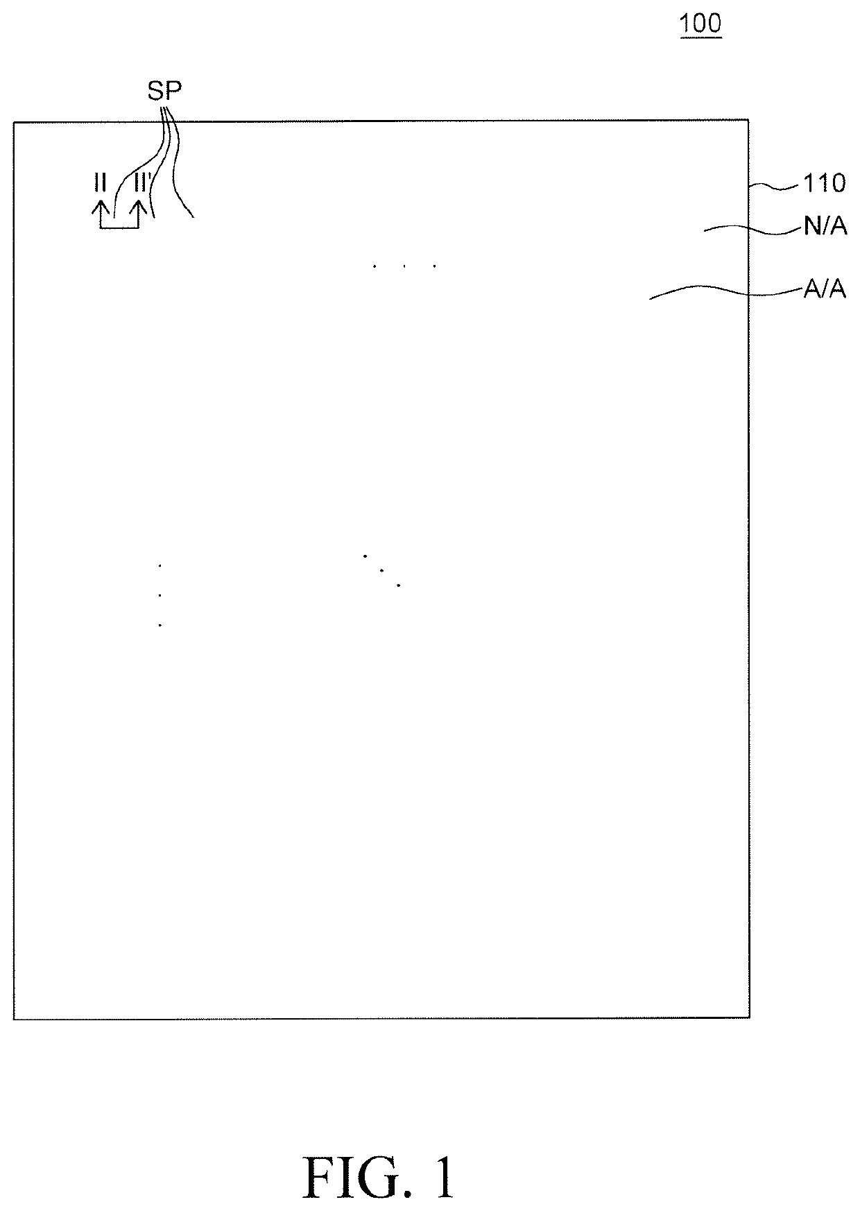
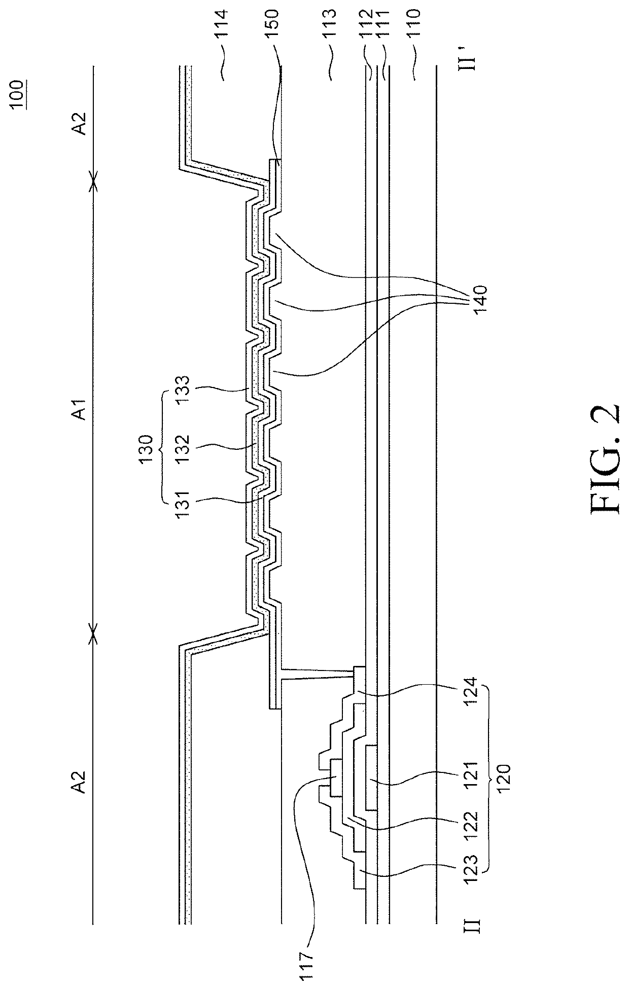
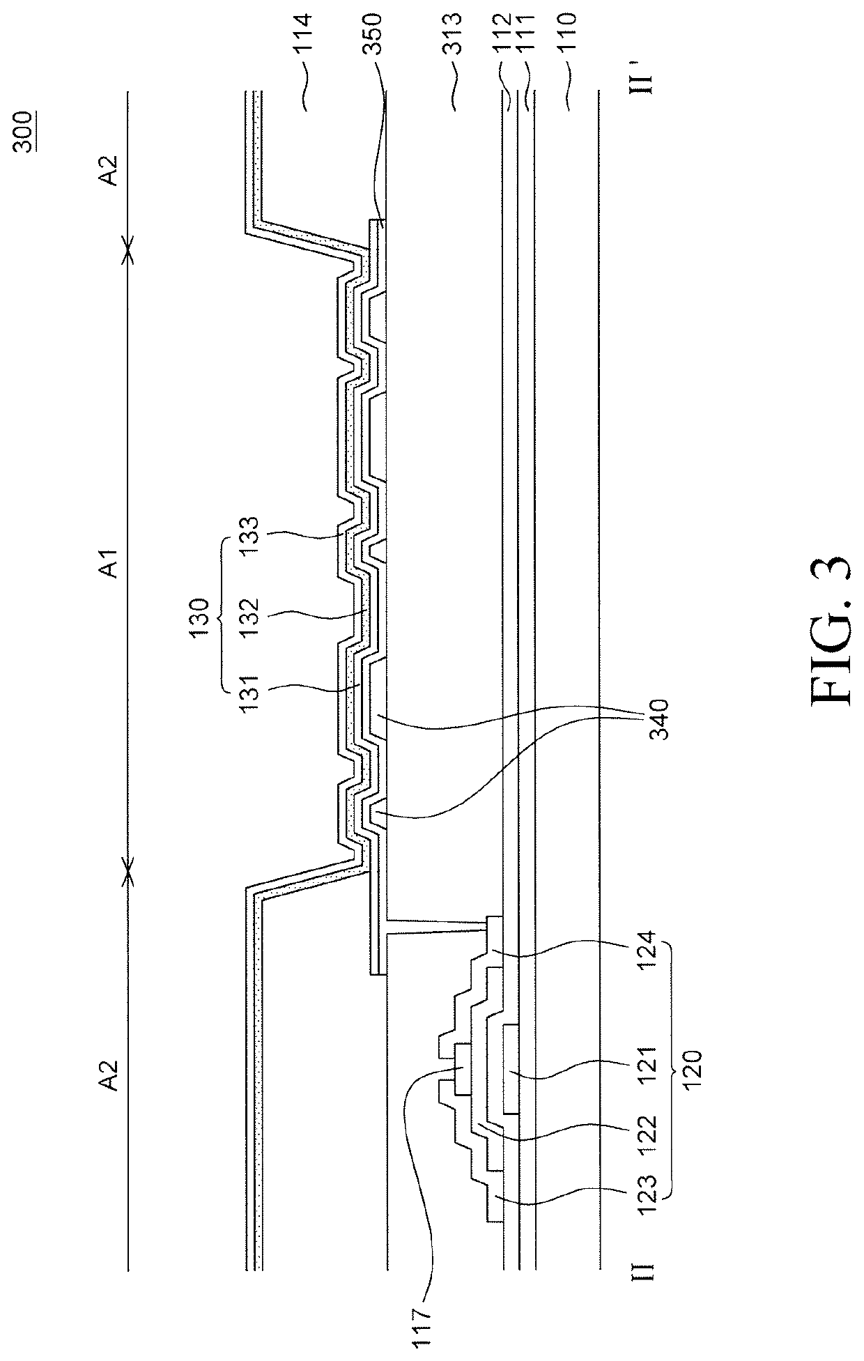
[0029]Advantages and characteristics of the present disclosure and a method of achieving the advantages and characteristics will be clear by referring to embodiments described below in detail together with the accompanying drawings. However, the present disclosure is not limited to the embodiments disclosed herein but will be implemented in various forms. The embodiments are provided by way of example only so that those skilled in the art can fully understand the disclosures of the present disclosure and the scope of the present disclosure. Therefore, the present disclosure will be defined only by the scope of the appended claims.

[0030]The shapes, sizes, ratios, angles, numbers, and the like illustrated in the accompanying drawings for describing the embodiments of the present disclosure are merely examples, and the present disclosure is not limited thereto. Like reference numerals generally denote like elements throughout the specification. Further, in the following description of ...


PUM

PropertyMeasurementUnit
emission areaaaaaaaaaaa
sizesaaaaaaaaaa
shapeaaaaaaaaaa

Abstract

A light emitting display apparatus can include a substrate; an over coating layer disposed on the substrate; a plurality of structures on the over coating layer, each of the plurality of structures including a flat upper surface; a reflective layer disposed on the plurality of structures; and a light emitting element disposed on the plurality of structures and the reflective layer.

Description

CROSS-REFERENCE TO RELATED APPLICATIONS[0001]This application claims the priority of Korean Patent Application No. 10-2018-0130270 filed on Oct. 29, 2018, in the Republic of Korea, the entirety of which is incorporated herein by reference.BACKGROUNDTechnical Field[0002]The present disclosure relates to a light emitting display apparatus, and more particularly, to a light emitting display apparatus which is capable of improving light extraction efficiency, improving outdoor visibility, and achieving a micro cavity effect.Description of the Related Art[0003]Currently, as society enters a full-scale information era, a field for display apparatuses which visually express electrical information signals has been rapidly developed and studies continue to improve performance of various display apparatuses, such as a thin-thickness, a light weight, and low power consumption.[0004]Among various display apparatus, a light emitting display apparatus is a self-emitting display apparatus so that ...

Claims


Application Information

Patent Timeline
Patent Type & Authority Patents(United States)
IPC IPC(8): H01L51/52H01L27/32
CPCH01L51/5265H01L27/3246H01L27/3258H01L51/5271H01L2251/5315H10K59/80521H10K59/80515H10K59/80518H10K59/876H10K59/878H10K59/875H10K59/124H10K2102/3026H10K50/852H10K50/856H10K59/122
Inventor KIM, NAMSU
Owner LG DISPLAY CO LTD
Learn More