Post-combustion carbon dioxide capture and compression

a carbon dioxide and post-combustion technology, applied in the field of post-combustion carbon dioxide capture and compression, can solve the problems of not being considered economically viable, and achieve the effect of maximising energy utilisation

Active Publication Date: 2022-01-18
LINDE AG
View PDF6 Cites 0 Cited by
  • Summary
  • Abstract
  • Description
  • Claims
  • Application Information

AI Technical Summary

Benefits of technology

[0014]One of the major challenges in post combustion carbon capture technologies is the high amount of thermal energy required for solvent regeneration in a scrubber which significantly reduces net power generation efficiency of power plants with carbon dioxide capture. This thermal energy can be provided by condensing a low pressure steam extracted from an intermediate pressure steam turbine, as also shown in FIG. 1 described below, while cooling water is typically used for inter-stage coolers for the multistage carbon dioxide compression.
[0028]A highly preferred variant of the embodiments just described include that the combustion air used in the high pressure steam generating unit is initially fully heated using sensible heat of the flue gas transferred from the flue gas downstream of the one treatment unit or downstream of one of the more than one treatment units and that the combustion air used in the high pressure steam generating unit is afterwards partially further heated using sensible heat of the flue gas transferred from the flue gas downstream of the high pressure steam generating unit and upstream of the one or more treatment units. This allows for the generation of low pressure steam at temperatures equal or greater than 160° C. and pressures equal or greater than 5 bara which is generally sufficient for the entire solvent regeneration of the plant. The part of the air not further heated using sensible heat of the flue gas transferred from the flue gas downstream of the high pressure steam generating unit and upstream of the one or more treatment units may be used in a different part of the high pressure steam generating unit than the part further heated. Particularly, the part not further heated may be directly introduced into the high pressure steam generating unit and the part further heated may be admixed to the fuel and may be introduced together with the fuel into the high pressure steam generating unit.

Problems solved by technology

As mentioned in the article cited, although the manufacture of carbon dioxide by this method was previously of a considerable commercial importance, it is now often not considered economically viable.

Method used


Image

  • Post-combustion carbon dioxide capture and compression
  • Post-combustion carbon dioxide capture and compression
  • Post-combustion carbon dioxide capture and compression

Examples


Embodiment Construction

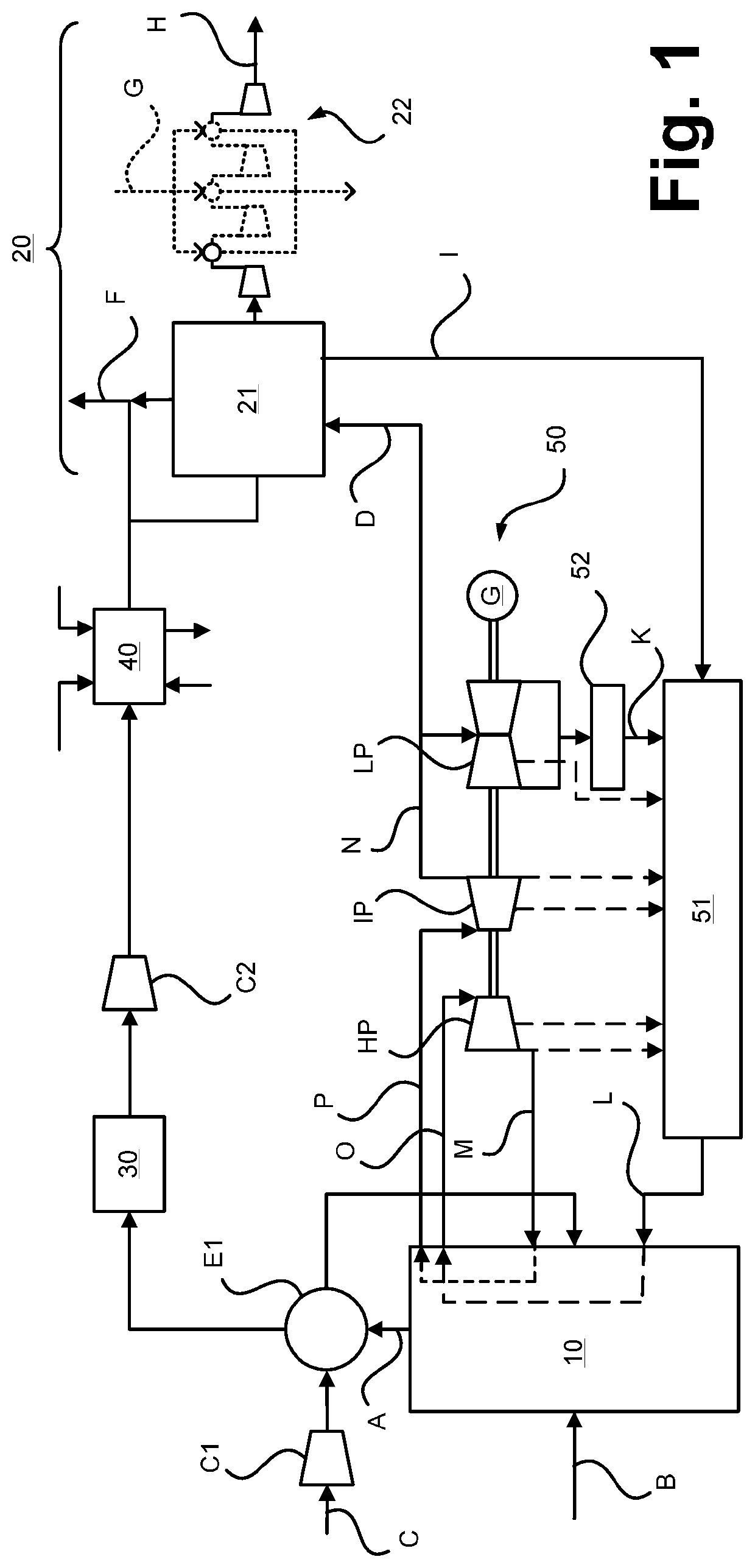
[0037]FIG. 1 illustrates a non-inventive method in which a flue gas containing carbon dioxide is provided and in which the carbon dioxide in the flue gas is at least partially captured and compressed.

[0038]In the method according to FIG. 1, a carbon dioxide containing flue gas stream A is provided by combusting a carbonaceous fuel B, e.g. coal, in a high pressure steam generating unit 10 using combustion air C which is also supplied to the high pressure steam generating unit 10. As mentioned, the high pressure steam generating unit 10 may comprise one or more steam boilers, burners and the like. The combustion air C is compressed in a combustion air compressor C1 and thereafter heated in a heat exchanger E1 using sensible heat of the flue gas stream A. The flue gas stream A is, after being passed through the heat exchanger E1, transferred to a particle removal unit 30 which may comprise an electrostatic precipitator or a filter arrangement (“bag house”). After slightly compressing t...


PUM

PropertyMeasurementUnit
temperatureaaaaaaaaaa

Abstract

A method is provided in which a carbon dioxide containing flue gas is provided by combusting a carbonaceous fuel in a high pressure steam generating unit using combustion air, and in which the carbon dioxide in the flue gas is at least partially captured and compressed in a carbon dioxide capture and compression unit having a carbon dioxide scrubber operated with an absorbing liquid which is regenerated using low pressure steam. The combustion air used in the high pressure steam generating unit is at least partially heated using sensible heat of the flue gas and / or the steam used for regenerating the absorption liquid of the carbon dioxide scrubber is at least partially generated using sensible heat of the flue gas. A corresponding system is also described herein.

Description

BACKGROUND OF THE INVENTION[0001]The present invention relates to a method in which a carbon dioxide containing flue gas is provided and in which the carbon dioxide in the flue gas is at least partially captured and compressed. The present invention also relates to a corresponding system.[0002]Capturing carbon dioxide from combustion flue gases is known. As e.g. outlined in the article “Carbon Dioxide” in Ullmann's Encyclopedia of Industrial Chemistry, online publication 30 May 2014, doi: 10.1002 / 14356007.a05_165.pub2, section 6.2, “Carbon Dioxide from Flue Gases,” carbon dioxide is a component of all flue gases produced by the complete combustion of carbonaceous fuels. Carbon dioxide concentrations in such gases are typically in the range of 10 to 18 vol %. They can be higher when a so-called oxygen-enriched combustion is performed.[0003]For capturing carbon dioxide, flue gases are typically cleaned from particles and passed through a water scrubber and / or a flue gas desulphurisati...

Claims


Application Information

Patent Timeline
Patent Type & Authority Patents(United States)
IPC IPC(8): B01D53/62B01D53/14B01D53/48B01D53/96B01D53/18
CPCB01D53/1475B01D53/1406B01D53/1418B01D53/1425B01D53/48B01D53/62B01D53/96B01D53/18B01D2252/10B01D2252/204B01D2257/504B01D2258/0283B01D2252/20405B01D2252/20484B01D2252/20421Y02A50/20Y02C20/40
Inventor JOVANOVIC, STEVANKRISHNAMURTHY, RAMACHANDRAN KRISH
Owner LINDE AG
Why Eureka
Try Eureka