Locking mechanism with push- and pull-to-release function and device comprising such locking mechanism

a technology of locking mechanism and function, applied in the field of locking, can solve problems such as damage, and achieve the effects of reducing the risk of damag

Active Publication Date: 2022-01-25
KONINKLJIJKE PHILIPS NV
View PDF15 Cites 0 Cited by
  • Summary
  • Abstract
  • Description
  • Claims
  • Application Information

AI Technical Summary

Benefits of technology

[0031]In an embodiment of the locking member according to the invention, the supporting member is pivotally mounted in relation to the track structure and is pivotable from the first position to the second position against action of the further biasing force. Such a pivotal mounting provides a compact and easy-to-manufacture design of the locking mechanism, and provides a well-defined movement of the supporting member.
[0034]In these embodiments, the obliquely extending supporting surface and the sloped surface of the guided element facilitate the displacement of the supporting member from its first position to its second position under the influence of an external pulling force to release the fifth track portion in order to enable the guided element to be displaced via the fifth track portion. This will be described in further detail in relation to the different embodiments shown in the figures.
[0036]In a further embodiment of the locking member according to the invention, the supporting member and the further biasing member are integrally formed. Thereby, a simplified structure of the locking member is achieved with a reduced number of components. In a still further embodiment of the invention, the further biasing member may comprise a leaf spring, and the supporting member may be provided on an end portion of the leaf spring which is deflectable at least with a deflection component perpendicular to the biasing direction. Such a leaf spring may typically be made from metal. The leaf spring has been found by the inventors to provide a reliable functioning of the locking mechanism. In the locked condition of the locking mechanism with the guided element in the third track position, the leaf spring is deflected by the guided element under the influence of a sufficiently large pulling force exerted on the locking mechanism, so that the leaf spring releases the fifth track portion to enable the guided element to be displaced via the fifth track portion. In an embodiment with such a leaf spring, the supporting member may be integrally formed with the leaf spring. Thereby, the manufacturing process of the locking mechanism may be further simplified, and the reliable functioning of the locking mechanism is further ensured. Alternatively, the supporting member may mounted on the leaf spring as a separate component, e.g. by means of an adhesive.
[0039]In an embodiment of the locking member according to the invention, the guiding structure has a stationary position, the first locking member is displaceable relative to the guiding structure with at least said displacement component parallel to the biasing direction, the biasing member acts the biasing force on the first locking member, and the guided element is provided on a carrier which is hingedly connected to the guiding structure. By providing the guided element on said carrier which is hingedly connected to the stationary guiding structure, the guided element can easily and reliably follow the track structure which is part of the displaceable first locking member.

Problems solved by technology

It has turned out that some users find it confusing that, to un-lock the cleaning device, the movable contact member has to be pushed down in the same direction as to lock the device cleaning.
Thereby, the locking mechanism will at best not be un-locked, and at worst it will become damaged.

Method used


Image

  • Locking mechanism with push- and pull-to-release function and device comprising such locking mechanism
  • Locking mechanism with push- and pull-to-release function and device comprising such locking mechanism
  • Locking mechanism with push- and pull-to-release function and device comprising such locking mechanism

Examples


Embodiment Construction

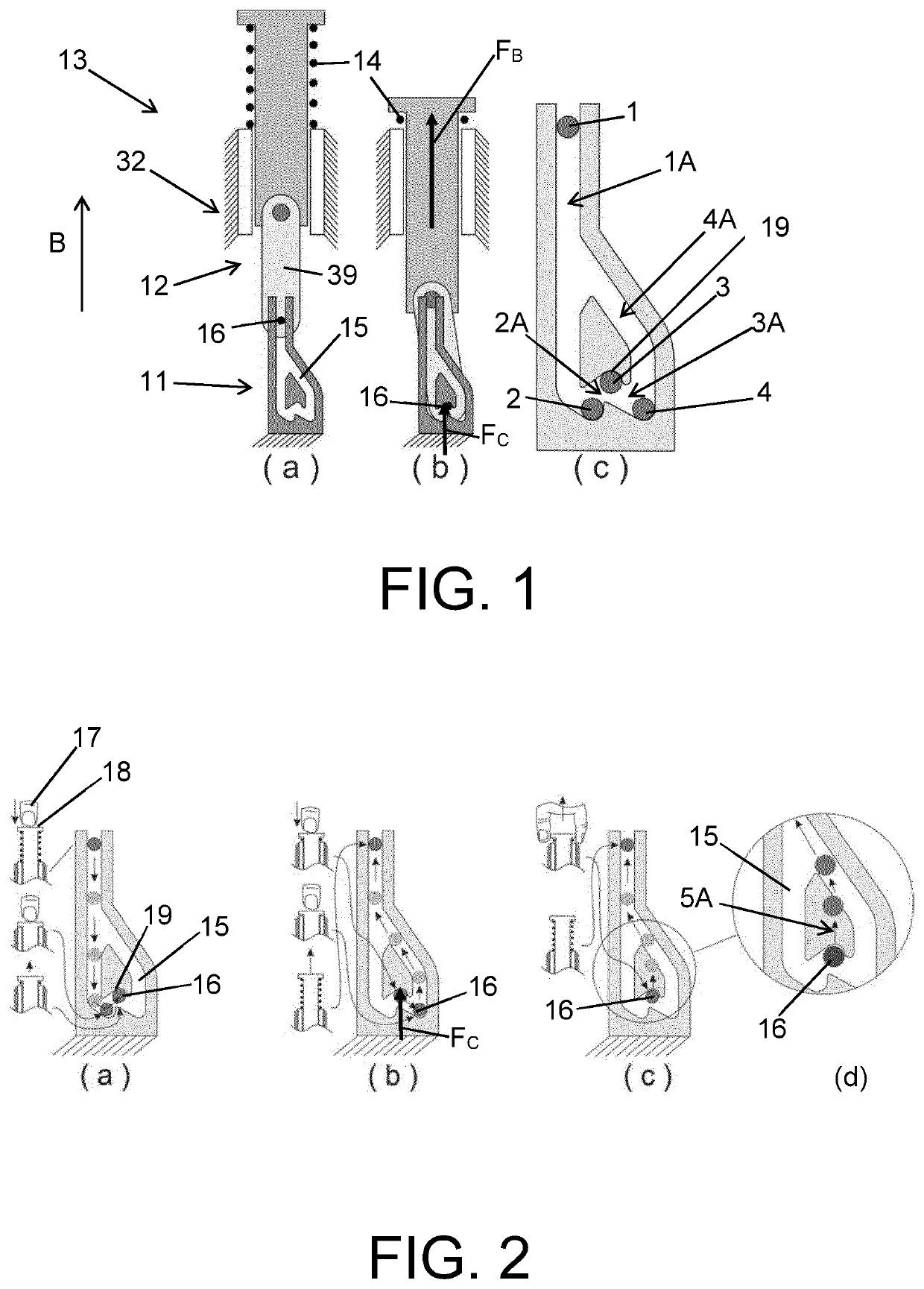
[0066]FIGS. 1a, 1b, 1c schematically show a known locking mechanism 13. It comprises a first locking member 11, a second locking member 12, and a biasing member 14 exerting, during operation, a biasing force FB on at least the first locking member 11 or the second locking member 12 in a biasing direction B. The biasing member 14 will typically be in the form of a spring which is compressed during operation of the locking member 13 whereby the biasing force FB is established. The locking mechanism 13 comprises a stationary guiding structure 32 for mutually guiding the first and second locking members 11,12 such that the first and second locking members 11,12 are mutually displaceable with at least a displacement component parallel to the biasing direction B. The first locking member 11 comprises a track structure 15 and the second locking member 12 comprises a guided element 16 guided by the track structure 15. FIG. 1a shows the locking mechanism 13 in an un-locked condition, and FIG...


PUM


Abstract

The present invention relates to a locking mechanism (13) comprising a first locking member (11), a second locking member (12), and a biasing member (14) exerting, during operation, a biasing force (FB) on at least the first locking member (11) or the second locking member (12) in a biasing direction (B). The locking mechanism further comprises a guiding structure (32) for mutually guiding the first and second locking members (11, 12), wherein the first locking member (11) comprises a track structure (15) and the second locking member (12) comprises a guided element (16) guided by the track structure (15). The locking mechanism (13) is moved from an un-locked to a locked condition by applying a pushing force to at least one of the first and second locking members (11, 12). The locking mechanism (13) can be moved from the locked to the un-locked condition by applying either a pushing or a pulling force to at least one of the first and second locking members (11, 12). The invention further relates to a device comprising such a locking mechanism (13). Such a device may be a holding device (40) for a shaving apparatus (24), for example a cleaning device for cleaning a shaving head (26) of a shaving apparatus (24).

Description

[0001]This application is the U.S. National Phase application under 35 U.S.C. § 371 of International Application No. PCT / EP2017 / 070025, filed on Aug. 8, 2017, which claims the benefit of International Application No. 16183427.0 filed on Aug. 9, 2016. These applications are hereby incorporated by reference herein.FIELD OF THE INVENTION[0002]The present invention relates to a locking mechanism comprising a first locking member, a second locking member, a biasing member exerting a biasing force on at least the first locking member or the second locking member in a biasing direction, and a guiding structure for mutually guiding the first and second locking members such that the first and second locking members are mutually displaceable with at least a displacement component parallel to the biasing direction, wherein the first locking member comprises a track structure and the second locking member comprises a guided element guided by the track structure, wherein the track structure comp...

Claims


Application Information

Patent Timeline
Patent Type & Authority Patents(United States)
IPC IPC(8): H01H13/56A45D27/29E05C19/02
CPCA45D27/29E05C19/022H01H13/562
Inventor DURKSZ, HEDZERBARON, SINTHEEREMA, GERTKUPERUS, JOHAN BERNARDMALTHA, KRIJN
Owner KONINKLJIJKE PHILIPS NV
Why Eureka
Try Eureka