Electrode device

a technology of electrodes and electrodes, applied in the direction of sensors, printed circuit aspects, diagnostics, etc., can solve the problems of increasing the operating time and further, and achieve the effects of less susceptibility to corrosion, improved signal quality, and cost-efficient formation

Active Publication Date: 2022-01-25
BITTIUM BIOSIGNALS OY
View PDF6 Cites 0 Cited by
  • Summary
  • Abstract
  • Description
  • Claims
  • Application Information

AI Technical Summary

Benefits of technology

[0005]The PCB may comprise a cantilever formed to the PCB, and the solder pads for the connector may be positioned to the tip of the cantilever. As the cantilever is formed out of the flexible PCB, the cantilever is able to bend, and therefore, the connector can be positioned on an opposite side of the electrodes. In this manner, a compact device with electrodes on one side and a connector on the other can be cost-efficiently formed with a single-sided PCB.
[0006]Further, the electrodes, traces, and solder pads may be made of copper, for example, and provided with a gold-plating and a solder mask leaving only the electrodes and solder pads exposed. This provides low-impedance connections between the electrodes and the solder pads, thereby improving signal quality. The gold plating also makes the electrode device less susceptive to corrosion so that the electrode device is able to maintain its good signal characteristics longer. The gold-plating may be formed before the solder mask, and the openings for the electrodes in the solder mask may be made smaller than the electrodes so that the solder mask overlaps the electrodes in the periphery of the electrodes. In this manner, when the electrode device is attached to skin of a person, only gold plated surfaces of the electrodes are in contact with the skin, and skin irritation can be minimized. Further, the above-described structure maximizes water resistance, thereby further increasing the operating time.
[0007]The PCB-based structure is also very robust. The copper traces and the gold plating can withstand bending well, and therefore the electrode device is not prone to breaking e.g. during movements of skin and / or removal of measurement electronics for recharging.

Problems solved by technology
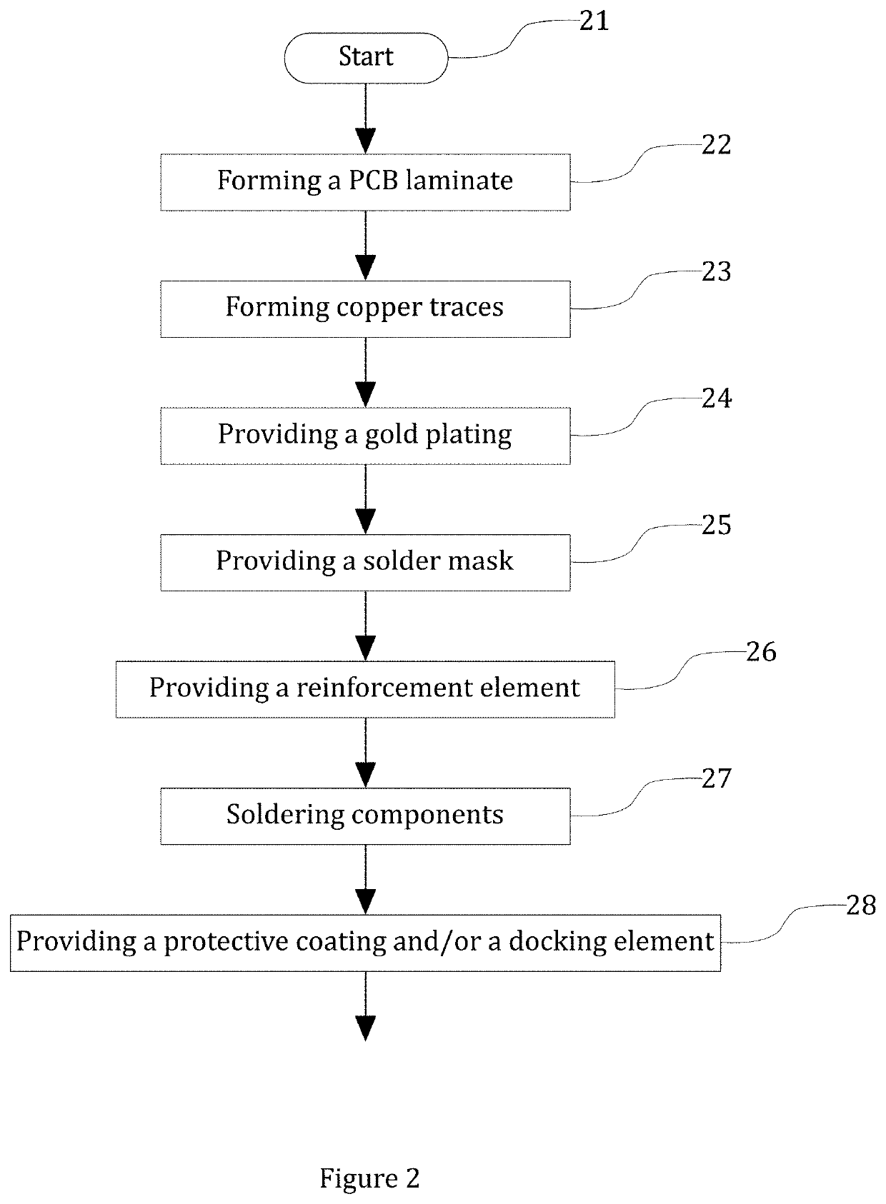
Further, the above-described structure maximizes water resistance, thereby further increasing the operating time.

Method used


Image

  • Electrode device
  • Electrode device

Examples


Embodiment Construction

[0011]The present disclosure describes an electrode device for measuring an electric biosignal. In the context of the present disclosure, an electric biosignal may be a signal that can be consistently, non-invasively measured and monitored from a human body with electrodes. Electroencephalography (EEG) and electrocardiography (ECG) are examples of electrical biosignals.

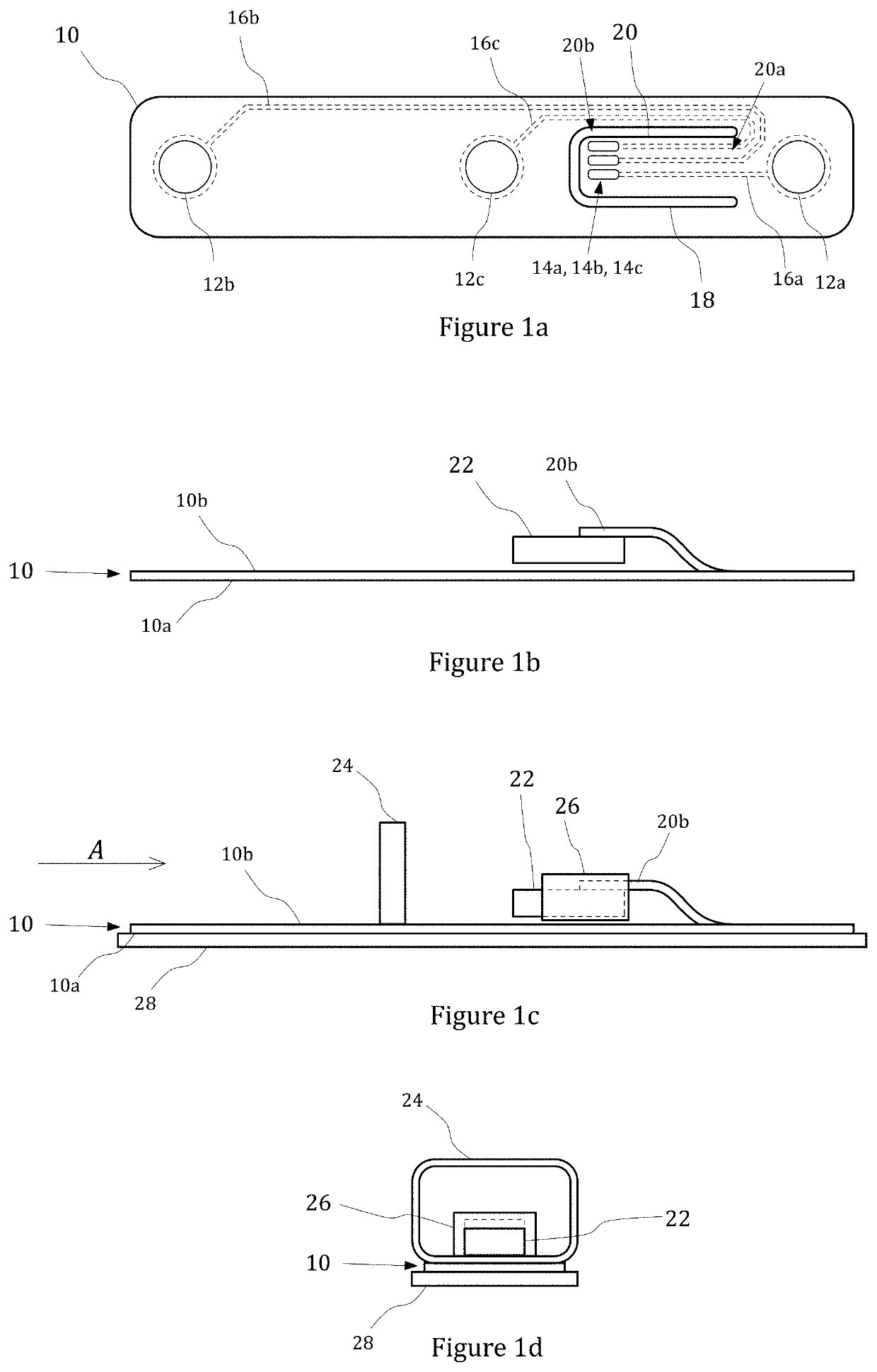
[0012]An electrode device according to the present disclosure comprises flexible PCB (printed circuit board) having at least a flexible support layer and a trace layer on a first side of the flexible PCB, and a connector component on an second side of the flexible PCB opposite to the first side. FIGS. 1a to 1d show simplified views of an embodiment of electrode device according to the present disclosure. FIG. 1a shows a bottom view of a flexible PCB 10 without a connector. The PCB 10 is in the form of an elongated, rectangular strip. The length of the PCB may be at least three times the width of the PCB, for example. ...


PUM


Abstract

Disclosed is an electrode device for measuring an electric biosignal. The electrode device includes a flexible PCB (printed circuit board) having a flexible support layer and a trace layer on a first side. The trace layer includes at least two electrode pads for skin contacts and, for each electrode pad, a solder pad and a conducting trace forming a galvanic connection between the electrode and the solder pad. The flexible PCB further includes an opening defining a flexible, elongated cantilever in a central portion of the flexible PCB, having a base end connected to the central portion and a free end separated from the central portion. The solder pads are located at the free end. The electrode device further includes a connector component on the second side, soldered to the solder pads on the free end of the cantilever.

Description

FIELD[0001]The invention relates to measurement of biosignals, and in particular, to measurement of electric biosignals with low-cost, flexible electrodes.BACKGROUND INFORMATION[0002]Low-cost, flexible electrodes are typically PET-based (Polyethylene terephthalate) structures with AgCl-based (silver chloride) electrodes. However, such electrodes break easily and do not tolerate well bending that occurs during normal use. Further, signal quality from such electrodes degrades quickly over time. Therefore, AgCl+PET electrodes are not well suited for longer measurements.BRIEF DISCLOSURE[0003]An object of the present disclosure is to provide an electrode device so as to alleviate the above disadvantages. This object is achieved by an electrode device which is characterized by what is stated in the independent claim. The preferred embodiments of the disclosure are disclosed in the dependent claims.[0004]A flexible PCB (printed circuit board) may be used as a basis for a cost-efficient, ro...

Claims


Application Information

Patent Timeline
Patent Type & Authority Patents(United States)
IPC IPC(8): A61B5/04A61B5/25H05K1/02H05K1/09H05K1/11H05K1/18H05K5/06A61B5/291
CPCA61B5/25A61B5/291H05K1/028H05K1/09H05K1/111H05K1/181H05K5/065A61B5/6831A61B5/6833A61B5/6838H05K1/118H05K2201/09081H05K2201/10189H05K2201/09445H05K2201/09145H05K2201/09063H05K2201/10909A61B5/24
Inventor MYLLYKANGAS, JUHA MATTI
Owner BITTIUM BIOSIGNALS OY
Why Eureka
Try Eureka