Mounting hub for antenna

a technology for mounting hubs and antennas, applied in the field of antennas, can solve problems such as significant time and material expenses

Active Publication Date: 2014-11-27
COMMSCOPE TECH LLC
View PDF7 Cites 5 Cited by
  • Summary
  • Abstract
  • Description
  • Claims
  • Application Information

AI Technical Summary

Problems solved by technology

Prior mounting hubs 8 have typically been fabricated via three-dimensional precision machining of

Method used


Image

  • Mounting hub for antenna
  • Mounting hub for antenna
  • Mounting hub for antenna

Examples


Embodiment Construction

[0019]The inventors have recognized that a hub mount may be formed from a common base frame provided with feet of varying dimensions, the frame and / or feet fabricated via two-dimensional methods, such as extrusion, to provide hub mounts for use with a wide range of reflector dish dimensions. Thereby the hub mount weight and hub mount manufacture, material and / or inventory costs may be reduced.

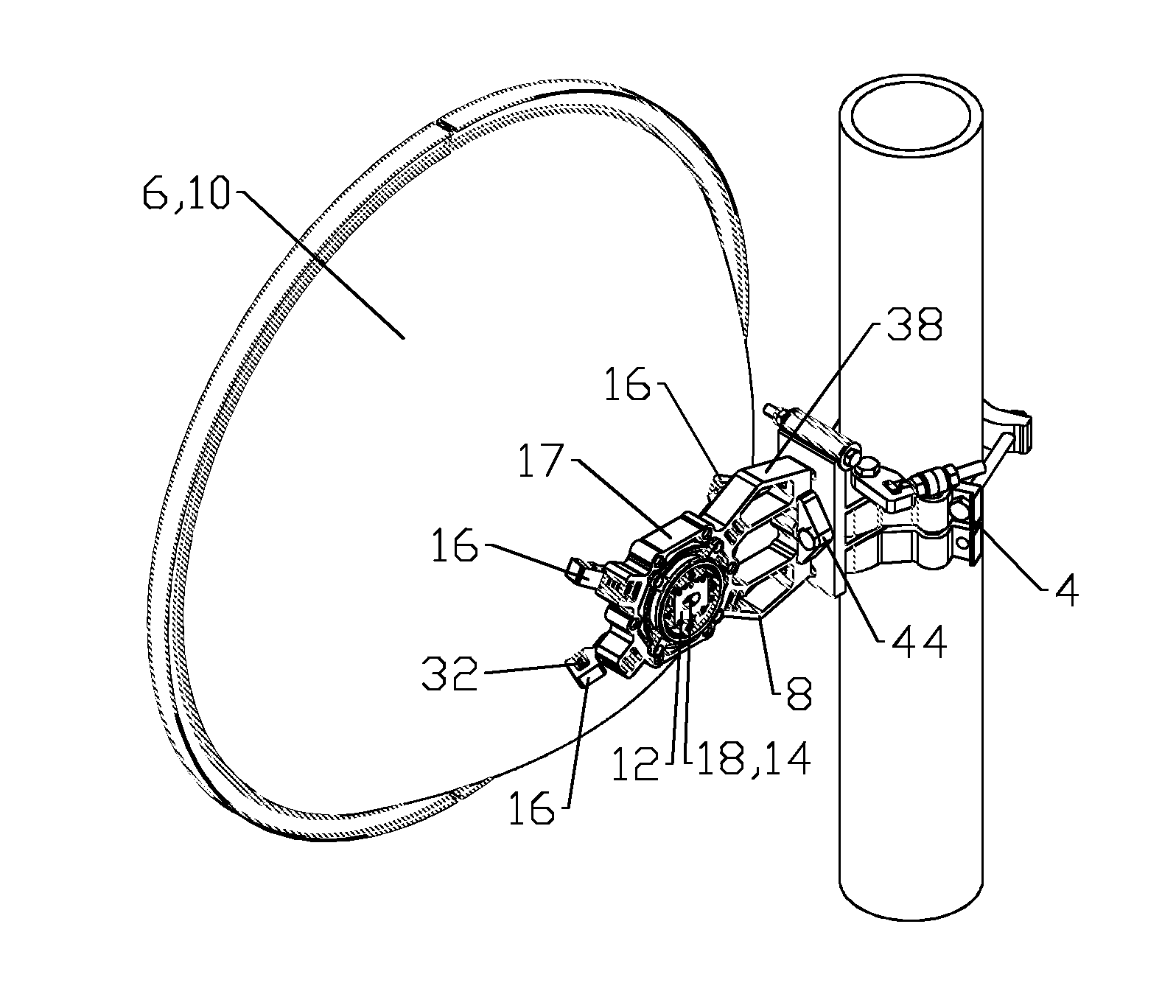
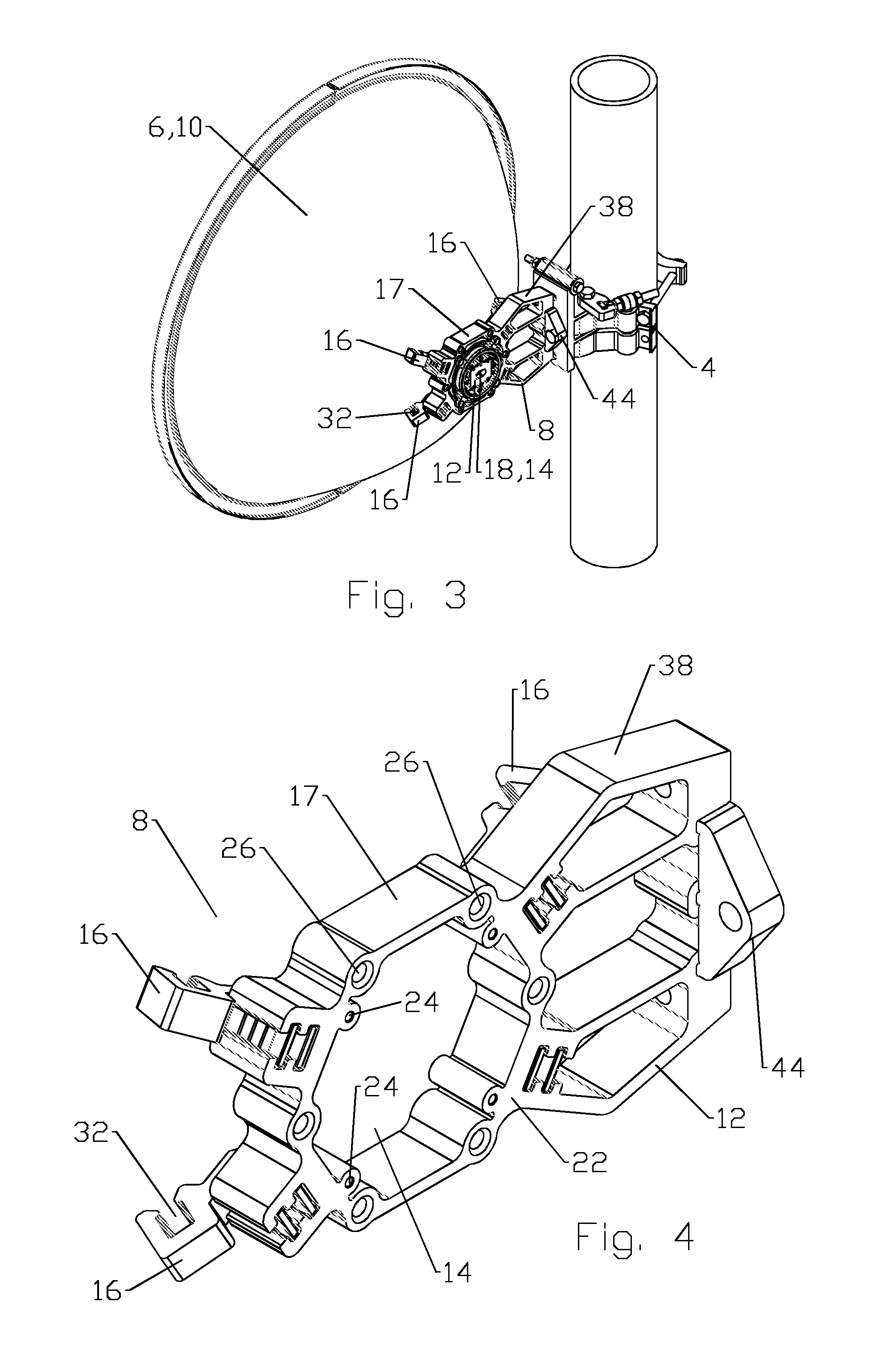
[0020]As shown for example in FIGS. 3-7, an exemplary embodiment of an antenna hub comprises a frame 12 with a feed aperture 14. As best shown in FIGS. 3 and 7, a plurality of feet 16, here demonstrated as four feet 16, are coupled to the frame 12; each of the feet 16 provided with a dish fastener coupling axis “A” normal to a surface of the reflector dish 10 contacting each foot 16 when the reflector dish 10 is seated upon the feet 16, a feed bore 18 of the reflector dish 10 aligned coaxial with the feed aperture 14.

[0021]Where a standardized feed aperture 14 is applied, varying reflector dish...


PUM

PropertyMeasurementUnit
Lengthaaaaaaaaaa
Adhesivityaaaaaaaaaa
Dimensionaaaaaaaaaa

Abstract

An antenna hub for a reflector dish has a frame with a feed aperture. A plurality of feet are coupled to the frame; each of the feet provided with a dish fastener coupling axis normal to a dish surface contacting each of the feet when the reflector dish is seated upon the feet, the feed bore of the reflector dish aligned coaxial with the feed aperture. The frame and feet may be formed via extrusion.

Description

BACKGROUND[0001]1. Field of the Invention[0002]This invention relates to antennas. More particularly, the invention relates to a mounting hub for coupling the antenna assembly, signal processing equipment and / or a mounting bracket of the antenna assembly to one another.[0003]2. Description of Related Art[0004]Reflector Antennas utilize a reflector dish to focus an RF signal upon a feed assembly such as a subreflector, waveguide and / or feed. The reflector dish, feed assembly and signal processing equipment such as a transceiver are typically coupled to one another via a mounting hub. Prior mounting hubs 8, for example as shown in FIGS. 1 and 2, have typically been provided for mating between a specific antenna mounting bracket 4, and reflector antenna 6, configured for unique dimensions of the reflector dish 10 and feed support plate combination, so that the mating points between the mounting hub 8 and the reflector dish 10 securely mate with the contours of the reflector dish 10, wi...

Claims


Application Information

Patent Timeline
IPC IPC(8): H01Q1/12
CPCH01Q1/1242H01Q1/1228Y10T29/4998
Inventor LEWRY, MATTHEW R.HUNTER, DOUGLAS P.WRIGHT, ALASTAIR D.
Owner COMMSCOPE TECH LLC
Why Eureka
Try Eureka