
Connector with Corrugated Cable Interface Insert

Active Publication Date: 2006-09-07
COMMSCOPE TECH LLC
View PDF8 Cites 43 Cited by
  • Summary
  • Abstract
  • Description
  • Claims
  • Application Information

AI Technical Summary

Benefits of technology

[0032] The insert 18 may be injection molded from conductive metal material, for example by thixotropic magnesium alloy metal injection molding. In this process, a powdered magnesium alloy is heated until it reaches a thixotropic state. The flowable material may then be molded similar to conventional polymer injection molding. The magnesium alloys used in thixotropic metal molding have desirable conductivity and rigidity characteristics and also have the benefit of being light in weight.
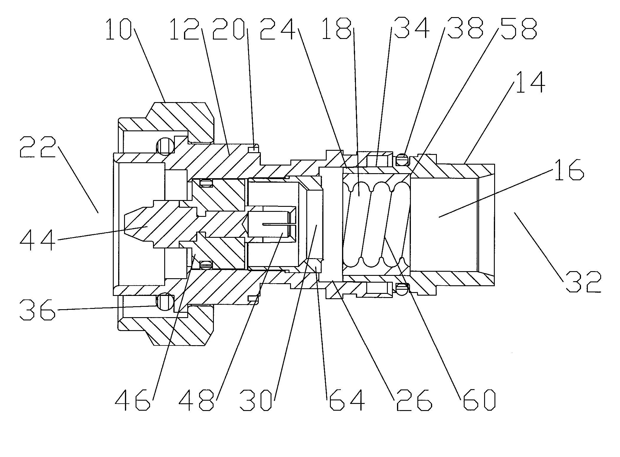
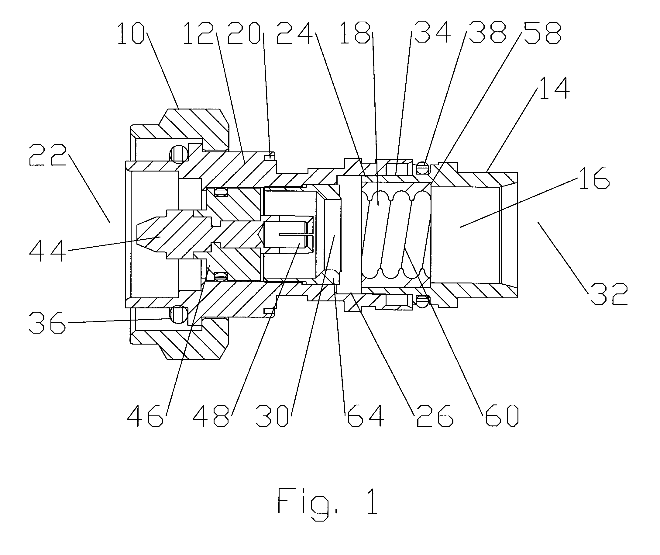
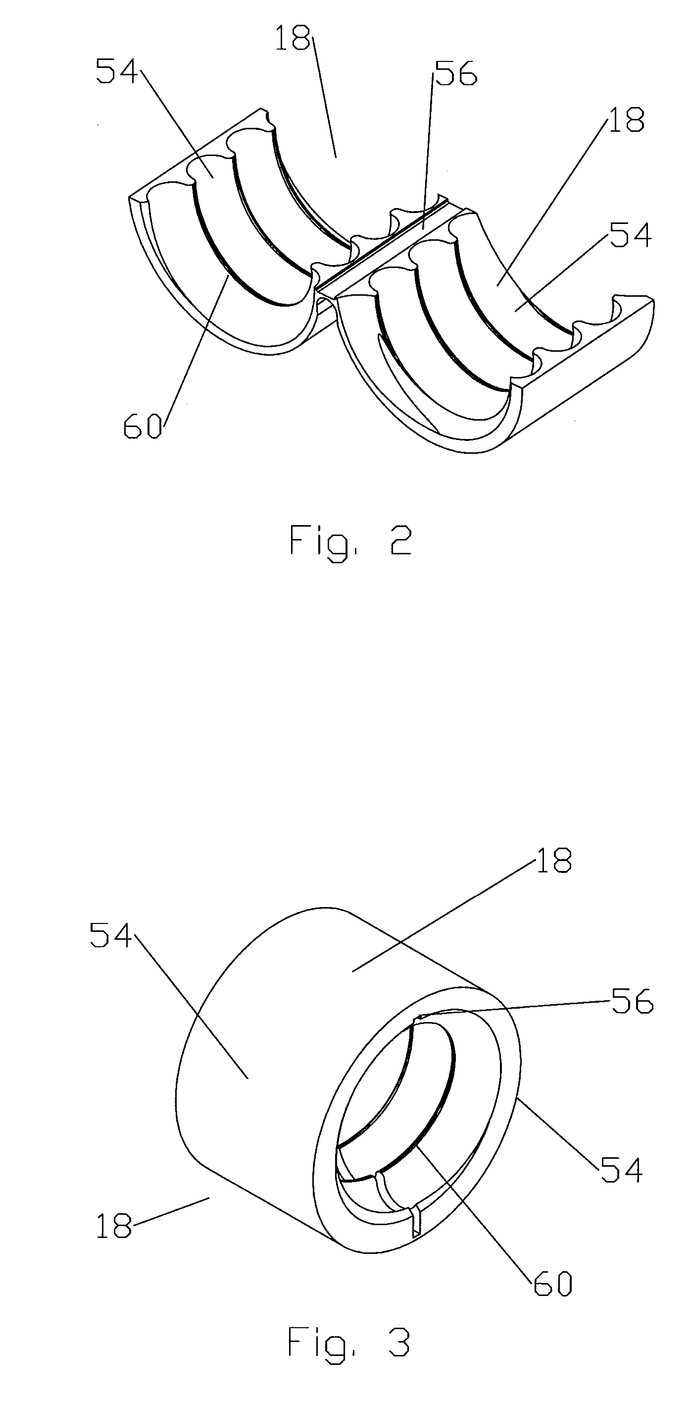
[0042] Through application of a range of different inserts 18, a single connector according to the invention may be used with any of a number of different coaxial cables having any desired outer conductor corrugation. Because the inserts 18 may be cost efficiently formed via simplified manufacturing methods such as stamping, casting and or injection molding, the prior need for additional clamping element(s) and or internal thread / corrugation machining operations upon the body bore 16 have been eliminated. Table of Parts10coupling nut12interface14body16body bore18insert20retention groove22connector end24interface mounting guide surface26body coupling surface30interface bore32cable end34interface mounting surface36first gasket38second gasket40third gasket42outer conductor44contact pin46insulator48spring finger50center conductor52cable54segment56hinge member58retaining shoulder60outer conductor projection62outer sheath64outer conductor stop

Problems solved by technology

These manufacturing operations comprise a significant portion of the overall manufacturing costs for the connectors.
Also, because the design relies upon threading the helical corrugations of the outer conductor into the connector body, to retain the cable within the body during and after final axial compression, it is not usable with annular corrugated cable.

Method used


Image

  • Connector with Corrugated Cable Interface Insert
  • Connector with Corrugated Cable Interface Insert
  • Connector with Corrugated Cable Interface Insert

Examples


Embodiment Construction

[0023] As shown for example in FIGS. 1-9, the invention will be described in detail via an exemplary embodiment for use with 50 ohm helically corrugated solid outer conductor coaxial cable. The exemplary embodiment is configured for a standard 7 / 16 DIN connector interface. Alternatively, the connector interface may be a proprietary configuration or a standard interface, for example, Type F, SMA, DIN, Type N or BNC.

[0024] As shown in FIG. 1, the connector has a coupling nut 10 upon an interface 12 that is coupled to a body 14 having a body bore 16 fitted with an insert 18. The coupling nut 10 may be retained upon the interface 12, for example, by deforming an outer edge of a cable end 32 facing retention groove 20 before or during an axial compression connector mounting step.

[0025] The exemplary embodiment is configured for interconnection in an interference fit via application of axial compression along a longitudinal axis of the connector. At the connector end 22 of the body 14, ...


PUM


Abstract

An electrical connector for coaxial cable having a corrugated solid outer conductor. The connector formed with a body having a bore with a retaining shoulder. An insert with a plurality of segment(s) having inward projecting projections arranged to mesh with the corrugated solid outer conductor. The segment(s) joined by at least one hinge member(s); the insert bendable along the hinge member(s) to fit within the bore, abutting the retaining shoulder. An interface is attachable to a connector end of the body. The interface having an inward projecting outer conductor stop. By exchanging the insert, the connector may be used with a range of cables having different outer conductor corrugation configurations.

Description

[0001] This application is a Continuation-In-Part of U.S. application Ser. No. 11 / 198,704 filed Sep. 5, 2005, currently pending, which is a Continuation of U.S. application Ser. No. 10 / 708,278 filed Feb. 20, 2004, now U.S. Pat. No. 6,939,169, which claims the benefit of U.S. Provisional Application No. 60 / 481,152 filed Jul. 28, 2003.BACKGROUND OF THE INVENTION [0002] 1. Field of the Invention [0003] The invention relates to an electrical connector. More particularly the invention relates to an electrical connector adaptable for use with coaxial cables having a variety of different outer conductor corrugations. [0004] 2. Description of Related Art [0005] Connectors for corrugated outer conductor cable are used throughout the semi-flexible corrugated coaxial cable industry. [0006] Solid outer conductor coaxial cables are available in two main groups of corrugation patterns, helical and annular. Typically, helical corrugation connector configurations are adapted to thread onto the corr...

Claims


Application Information

Patent Timeline
IPC IPC(8): H01R9/05H01R13/646
CPCH01R9/0524H01R13/501H01R13/502H01R13/514H01R13/5837H01R24/564H01R2103/00H01R9/05
Inventor PAYNTER, JEFFREY D.
Owner COMMSCOPE TECH LLC
Learn More