Image forming apparatus

a technology of forming apparatus and forming wall, which is applied in the field of image forming apparatus, can solve the problems image unevenness, and achieve the effect of reducing the non-uniformity of chargeability of the photosensitive drum, uniform dose distribution, and optimal height of the blocking wall

Active Publication Date: 2022-02-08
SHARP KK
View PDF5 Cites 0 Cited by
  • Summary
  • Abstract
  • Description
  • Claims
  • Application Information

AI Technical Summary

Benefits of technology

[0011]According to this configuration, the static elimination light emitted from the irradiation end surface is irradiated onto the photosensitive drum after being restricted by the blocking member. Portions of the static elimination light emitted from end regions located around ends of the light guide plate are less restricted by the blocking member than a portion emitted to a central region being a region other than the end regions of the light guide plate. According to this configuration, the static elimination light irradiated onto the photosensitive drum achieves a more uniform dose distribution throughout a length of the photosensitive drum in the axial direction (longitudinal direction) of the photosensitive drum. This reduces non-uniformity in chargeability of the photosensitive drum and image unevenness that can occur during image formation.
[0026]According to the present invention, it is possible to provide an image forming apparatus that achieves cost reduction, static elimination on a photosensitive drum with light having a uniform dose distribution, and prevention or reduction of image degradation.

Problems solved by technology

This reduces non-uniformity in chargeability of the photosensitive drum and image unevenness that can occur during image formation.

Method used


Image

  • Image forming apparatus
  • Image forming apparatus
  • Image forming apparatus

Examples


embodiment 1

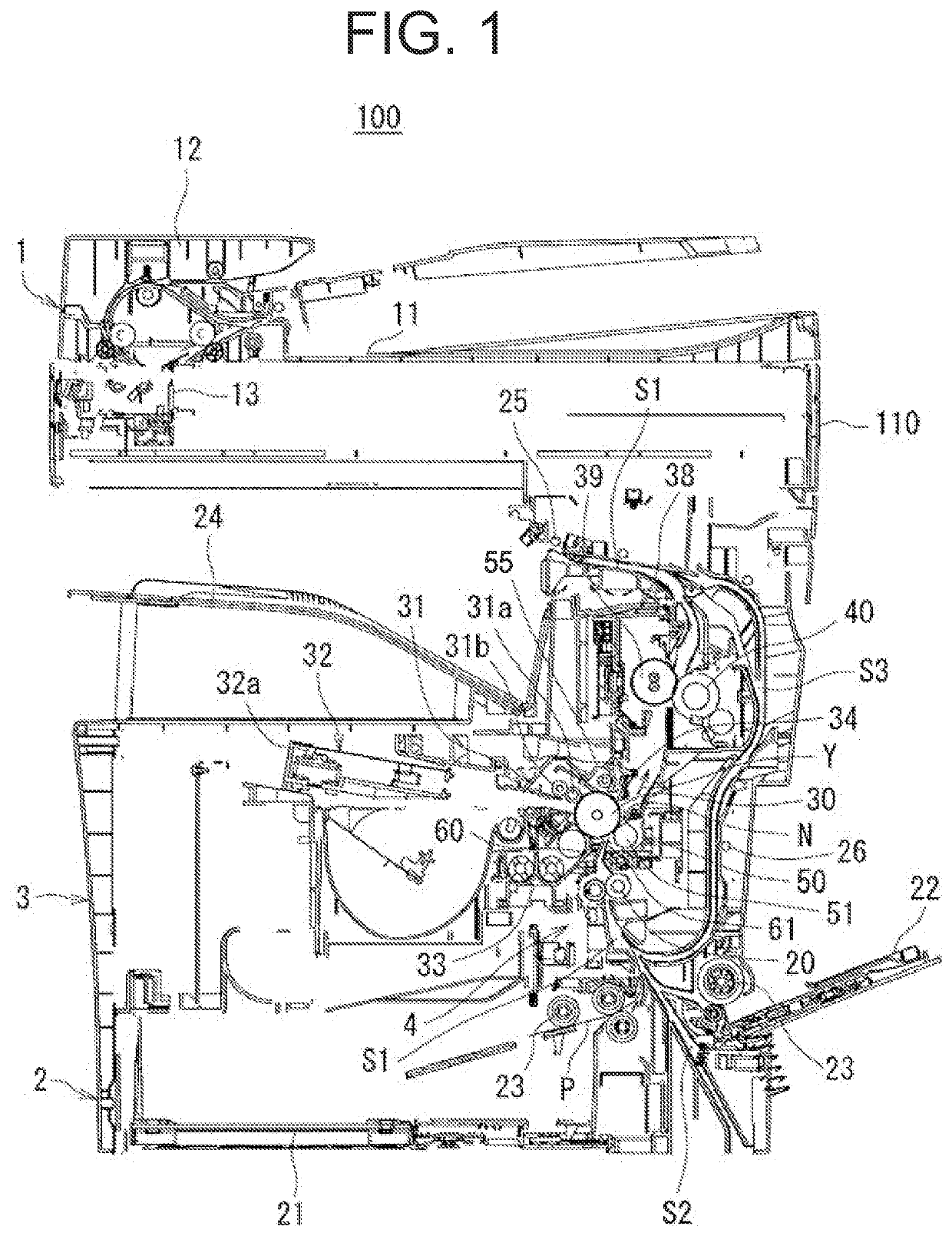
[0039]The following describes Embodiment 1 of the present invention in detail with reference to the accompanying drawings. FIG. 1 is a schematic cross-sectional view of an image forming apparatus 100 according to Embodiment 1 of the present invention.

[0040]The image forming apparatus 100 according to Embodiment 1 is an electrophotographic image forming apparatus, and includes an image reader 1, an image former 3 disposed under the image reader 1, and a paper feeder 2 disposed under the image former 3 as illustrated in FIG. 1.

[0041]The image reader 1 includes a document table 11 including transparent glass, an automatic document feeder (ADF) 12 that automatically feeds a document onto the document table 11, and a document image reader 13 that scans and reads an image of the document placed on the document table 11. The image former 3 is provided in an image forming apparatus main body 110. The image former 3 includes a photosensitive drum 30 (image bearing member) and various constit...

example 1

[0068]FIG. 4 is a schematic view illustrating a configuration of a static eliminator 34 according to Example 1 of the present invention as seen in a direction from the photosensitive drum 30 to the static eliminator 34. FIG. 5 is a diagram showing dose distribution of light L irradiated onto a photosensitive drum 30 according to Example 1 of the present invention. Note that components that have the same function and operation as the components that have already been described are labelled using the same reference signs, and detailed description thereof is omitted.

[0069]As illustrated in FIG. 4, the static eliminator 34 of an image forming apparatus 100 according to Example 1 has a blocking wall 36 disposed on an edge 35 of a housing 34c. Regions R101 and R102, which are end regions located around ends of a light guide plate 34b, are not provide with the blocking wall 36 on the edge 35, whereas a region R103, which is a central region located between the regions R101 and R102, is pro...

embodiment 2

[0083]The following describes an image forming apparatus according to Embodiment 2 of the present invention with reference to the drawings. Note that components that have the same function and operation as the components that have already been described are labelled using the same reference signs, and detailed description thereof is omitted.

[0084]FIG. 7 is a schematic view of a static eliminator 34 as seen in a direction from a photosensitive drum 30 to the static eliminator 34 in an image forming apparatus 100 according to Embodiment 2 of the present invention. The static eliminator 34 in Embodiment 2 has the same configuration as the static eliminator 34 in Embodiment 1 except that an edge 35 of a housing 34c in Embodiment 2 further has grooves 37 in portions thereof corresponding to ends of a light guide plate 34b.

[0085]The edge 35 of the housing 34c further includes the grooves 37 in the portions thereof corresponding to the ends of the light guide plate 34b as illustrated in F...


PUM

PropertyMeasurementUnit
heightaaaaaaaaaa
heightaaaaaaaaaa
heightaaaaaaaaaa

Abstract

An image forming apparatus includes: a photosensitive drum; a light guide plate that irradiates, onto the photosensitive drum, light incoming through an end thereof by emitting the light from an irradiation end surface thereof; a static elimination light source that is disposed near the end of the light guide plate and emits the light into the light guide plate; and a blocking wall that is disposed between the light guide plate and the photosensitive drum to cover the irradiation end surface, and restricts the light emitted from the irradiation end surface non-uniformly in a longitudinal direction of the light guide plate. Of the light emitted from the irradiation end surface, portions emitted from end regions located around ends of the light guide plate are less restricted by the blocking wall than a portion emitted from a region other than the end regions of the light guide plate.

Description

BACKGROUND OF THE INVENTIONField of the Invention[0001]The present invention relates to an image forming apparatus that performs static elimination on a photosensitive drum using light.Description of the Background Art[0002]It is conventional to eliminate static from a photosensitive drum by irradiating the photosensitive drum with light from a static elimination lamp in image forming apparatuses such as copiers, facsimile machines, printers, and multifunction peripherals. An image forming apparatus includes, for example, an image forming unit (image former), a transfer device, and a fixing device as an image forming mechanism. The image forming unit forms a toner image. The toner image formed is transferred onto paper. The fixing device fixes the transferred toner image to the paper. The paper having the image formed thereon is ejected out of the image forming apparatus.[0003]The image forming unit has a photosensitive drum, a development device, and the like. An electrostatic late...

Claims


Application Information

Patent Timeline
Patent Type & Authority Patents(United States)
IPC IPC(8): G03G21/08G03G21/00
CPCG03G21/08G03G21/0094
Inventor KAWAJIRI, KAZUKI
Owner SHARP KK
Why Eureka
Try Eureka