Gamma ray focusing radiation unit

A technology of focused irradiation and gamma ray, which is applied in the field of gamma ray focused irradiation unit, can solve the problems that affect the local control rate of tumor treatment, the accuracy of treatment, reduce the efficiency of user treatment plan, and the poor uniformity of dose in tumor target area, etc. Achieve the effects of reducing manufacturing cost and processing difficulty, easy adjustment, and uniform dose distribution

Inactive Publication Date: 2009-12-02
吕风华 +1
View PDF2 Cites 0 Cited by
  • Summary
  • Abstract
  • Description
  • Claims
  • Application Information

AI Technical Summary

Problems solved by technology

A common feature of them is that more than 20 CO60 radioactive sources are arranged on the source carrier of a rotary geometric shell. These radioactive sources are generally divided into 4-6 groups. On the shell of the source body, the longitude difference between each group of adjacent sources is 50-90°, and they are evenly distributed within the longitude of 0-360°. This arrangement is subject to treatment space due to latitude (the common focus must reach the sectional plane of the source body Outer distance) and the limitation of the distribution characteristics of the focal dose field, so that the number of collimation channels that can be installed on the collimation body (the type of field specification) is relatively small, and the products currently on the market can only be equipped with 2- 3 types
Fewer types of collimation channels will lead to poor uniformity of dose distribution in the tumor target area and difficulty in controlling the conformity in body tumor radiotherapy, thus affecting the local control rate of tumor treatment and the accuracy of treatment. Reduce the efficiency of users in formulating treatment plans

Method used


Image

  • Gamma ray focusing radiation unit
  • Gamma ray focusing radiation unit
  • Gamma ray focusing radiation unit

Examples


Embodiment Construction

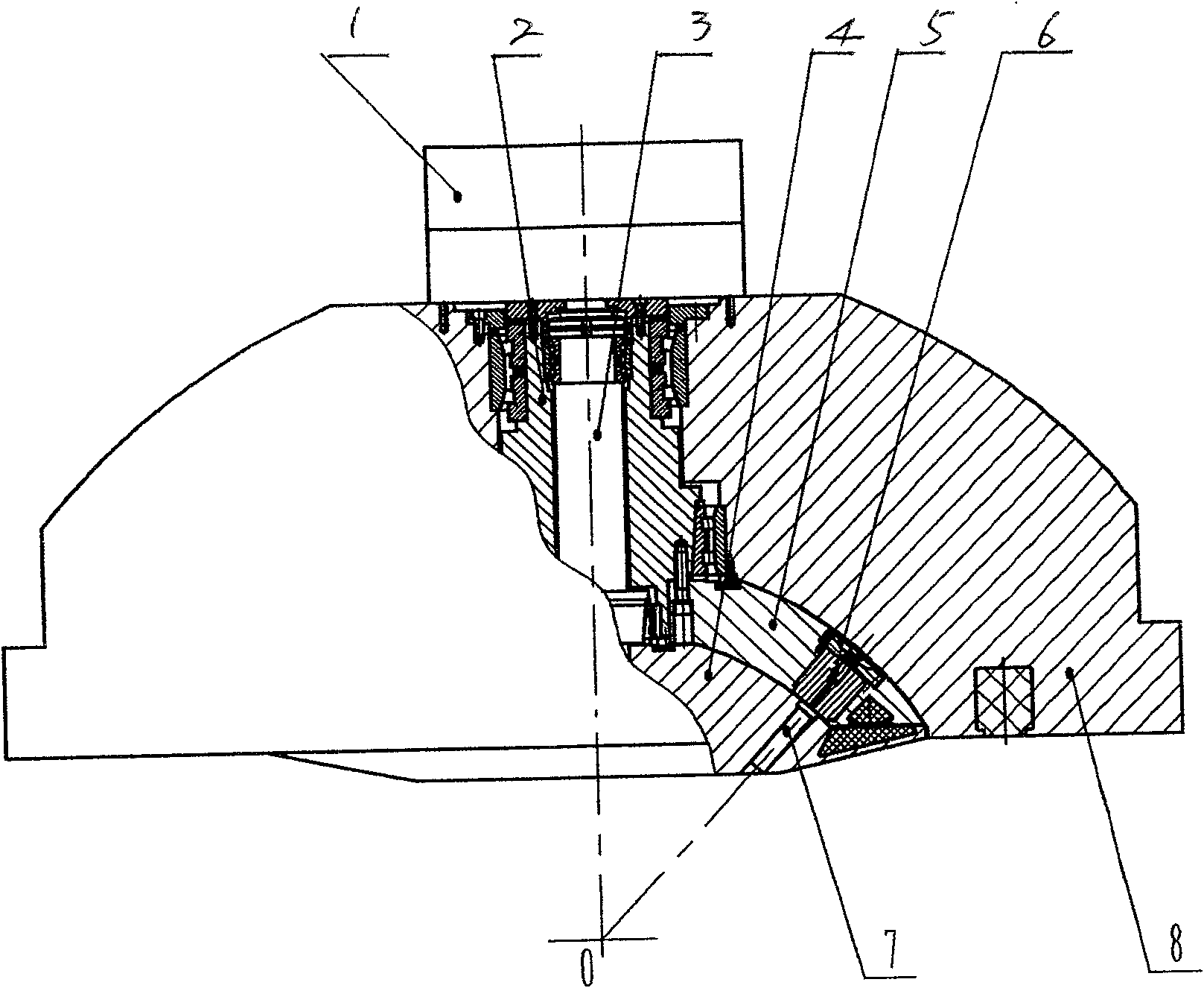
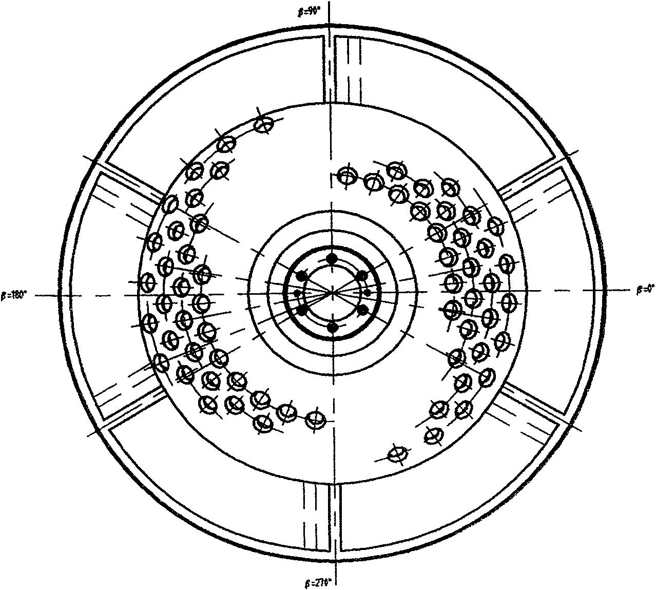
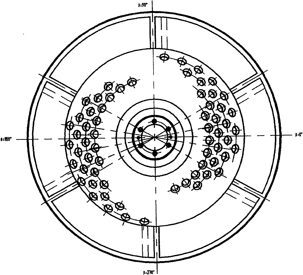
[0018] according to figure 1 As shown, in the radiation unit, the source body 5 is installed in the radiation protection body 8, and a group of Co60 radioactive sources 6 are installed on the source body 5, and these Co60 radioactive sources are all aimed at a common focal point O; the collimator 4 and The inner cavities of the source body 5 are connected, and several groups of basic collimators 7 are installed on the collimator body 4 . The rules are the same. figure 2 and image 3 It is an arrangement scheme of two kinds of radioactive sources. The source body 5 is composed of two symmetrical fan-shaped shells, on which eight radioactive sources are arranged and divided into two groups. They are symmetrically distributed on the source body 5. Each group emits The longitude range occupied by the source in space is 60 degrees, and the longitude difference between adjacent radioactive sources is 20 degrees. Figure 4 and Figure 5 With figure 2 , image 3 The arrangemen...


PUM


Abstract

A gamma ray focused irradiation unit, comprising: a shielding body, a source body, a collimator, and a transmission group, characterized in that: the source body is equipped with 8-12 radioactive sources and divided into two groups, each group of 4- 6 radioactive sources, two groups of radioactive sources are symmetrically distributed on two bar-shaped or fan-shaped shells with a longitude difference of 40-80°, thus forming a space arc with an opening angle greater than 130°, and multiple sets of collimators are installed on the collimator Collimator, the distribution law of the collimator is consistent with the distribution law of the radioactive source on the source body, the collimators of adjacent groups keep an interval of 15-20° in longitude, and keep an interval of 3-5° in latitude. Its advantages are: it can form a space arc with an opening angle greater than 130 degrees; and form arc rotation and aggregation; improve the uniformity of the dose in the target area and the efficiency of the equipment; the dose distribution is more uniform and the treatment is more precise; The number of sources reduces the manufacturing cost and processing difficulty.

Description

technical field [0001] The invention relates to the technical field of medical equipment, in particular to a gamma ray focused irradiation unit. Background technique [0002] The existing gamma ray stereotaxic therapy system (also known as gamma knife) is a kind of precise radiotherapy equipment, and their radiation units all adopt the principle of geometric focusing, the purpose of which is to use gamma ray to generate large doses of radiation to the lesion target. Irradiation, while minimizing the damage to normal tissues around the target, that is, increasing the therapeutic gain ratio during radiotherapy. To achieve this purpose, the existing gamma knives all adopt a plurality of CO60 radioactive sources distributed on a rotary geometry (source carrier) such as a sphere, and each radioactive source aligns the rays at a common focus through a collimating channel, thereby A high-dose zone is formed at the focal point. Such as CN1050062C, CN2590600Y, CN03125396, and other...

Claims


Application Information

Patent Timeline
Patent Type & Authority Patents(China)
IPC IPC(8): A61N5/00A61B18/18
Inventor 吕风华李萍
Owner 吕风华
Why Eureka
Try Eureka