Exposure dose uniformity by rotation, translation and variable process conditions

A technology of exposure dose and uniformity, applied in microlithography exposure equipment, photolithography exposure equipment, optics, etc., can solve problems such as light bar intensity attenuation

Active Publication Date: 2020-08-11
TOKYO ELECTRON LTD
View PDF6 Cites 0 Cited by
  • Summary
  • Abstract
  • Description
  • Claims
  • Application Information

AI Technical Summary

Problems solved by technology

However, light bars may have significant intensity falloff

Method used


Image

  • Exposure dose uniformity by rotation, translation and variable process conditions
  • Exposure dose uniformity by rotation, translation and variable process conditions
  • Exposure dose uniformity by rotation, translation and variable process conditions

Examples


Embodiment Construction

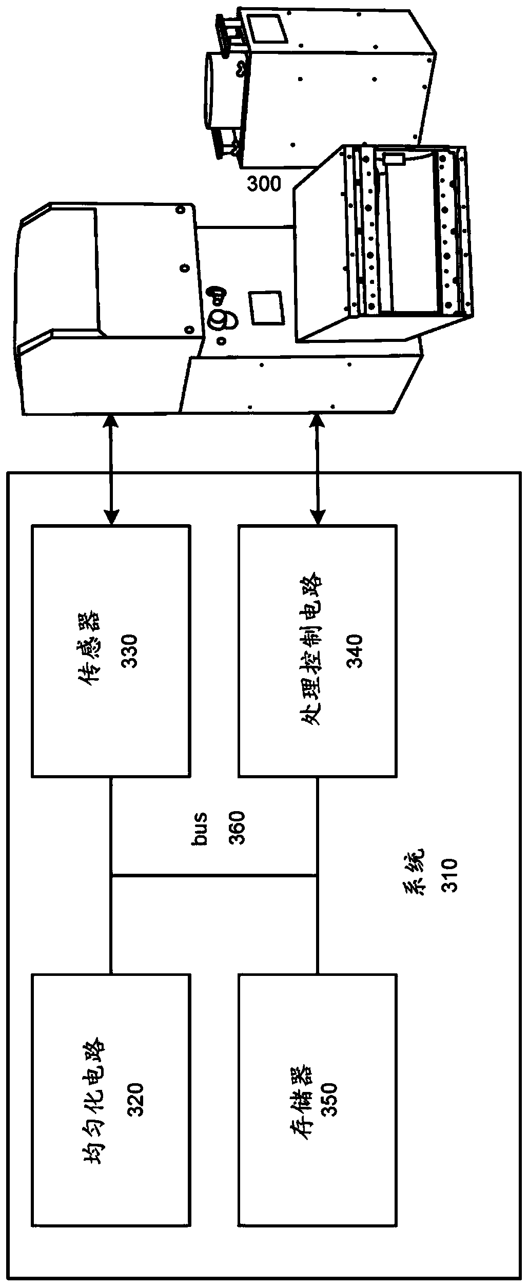
[0032] image 3 is a dose homogenization system 310 for a UV source 300 according to an embodiment of the invention. System 310 may include one or more processing circuits (eg, equalization circuit 320 and / or processing control circuit 340 ), one or more sensors 330 , memory 350 , and / or other elements. Sensor 330 may measure lamp intensity and decay of UV source 300 . Uniformization circuitry 320 may determine UV source 300 system settings to optimize UV ​​light quantitative uniformity. Process control circuitry 340 may control elements of UV source 300 (eg, motors, UV lights, etc.) to achieve a determined UV optimization. The functions and features of these elements 320-350 are described in more detail below. These elements 320 - 350 may be interconnected via a bus 360 . Some elements may be combined (eg, a single processing circuit may perform the functions of equalization circuit 320 and processing control circuit 340 in some embodiments). In some implementations, ele...


PUM


Abstract

The substrate may be disposed on a substrate support in a wafer exposure processing system. Exposure dose distribution over the entire film can be selected. The substrate can be exposed to flood radiation from the source, and flood irradiation can be terminated when a selected exposure dose profile is achieved. Exposing the substrate to flood radiation can include controlling the substrate rotation rate, source scan rate, substrate scan rate, source power settings, distance from source to substrate, source aperture settings, angle of incidence of flood radiation on the substrate, and source At least one of the focal positions to achieve the selected exposure dose distribution across the entire film.

Description

[0001] Cross References to Related Applications [0002] This disclosure claims U.S. Provisional Application No. 62 / 141,003, filed March 31, 2015, entitled "High Power UV Flood Exposure Dose Homogenization by Combination of Rotation, Translation and Variable Processing Conditions," and filed July 16, 2015 Priority to US Nonprovisional Patent Application Serial No. 14 / 801,703, entitled "Exposure dose homogenization through rotation, translation, and variable processing conditions," the entire contents of which are incorporated herein by reference. Background technique [0003] Substrate processing generally involves exposing the substrate wafer to radiation. For example, the substrate can be exposed to ultraviolet (UV) light, including high power UV radiation. The substrate may be exposed to high power light (eg UV light), for example, during a photolithography process and / or other fabrication processes. Exposing the entire substrate to a light source of substantially uniform...

Claims


Application Information

Patent Timeline
Patent Type & Authority Patents(China)
IPC IPC(8): G03F7/20
CPCG03F7/2022G03F7/70008
Inventor 马克·L·沙滕伯格鲁道夫·H·亨德尔迈克尔·卡尔卡西
Owner TOKYO ELECTRON LTD
Why Eureka
Try Eureka