
Image forming system, method for controlling power supply, and computer-readable recording medium

a technology of power supply and image forming system, which is applied in the field of image forming system, a control method of power supply, and a computer-readable recording medium, can solve the problems of user waiting, manual staple mechanism cannot be used, and user cannot use a manual staple mechanism immediately, so as to achieve the effect of suppressing an increase in the amount of power consumption

Active Publication Date: 2022-02-08
KONICA MINOLTA INC
View PDF11 Cites 0 Cited by
  • Summary
  • Abstract
  • Description
  • Claims
  • Application Information

AI Technical Summary

Benefits of technology

The present invention aims to provide an image forming system, a method for controlling power supply, and a computer-readable recording medium that can reduce power consumption and quickly perform manual staple processing.

Problems solved by technology

When a shift time to be taken until a sleep mode starts is set to be short to suppress power consumption in an image forming apparatus, the following problem may occur.
In this case, there may occur a situation where “a manual staple mechanism cannot be used because the image forming apparatus already enters the sleep mode (a sleep state, a power saving mode)”.
In addition, even in the configuration in Japanese Laid-Open Patent Publication No. 2014-162590, it is necessary to wait for the post-processing apparatus to return from the sleep mode, and thus there may occur a situation where the user cannot use a manual staple mechanism immediately.
Thus, the user has to wait for manual staple processing to become ready.
On the other hand, when the shift time to be taken until the sleep mode starts is set to be long, the amount of power consumption increases.

Method used


Image

  • Image forming system, method for controlling power supply, and computer-readable recording medium
  • Image forming system, method for controlling power supply, and computer-readable recording medium
  • Image forming system, method for controlling power supply, and computer-readable recording medium

Examples


Embodiment Construction

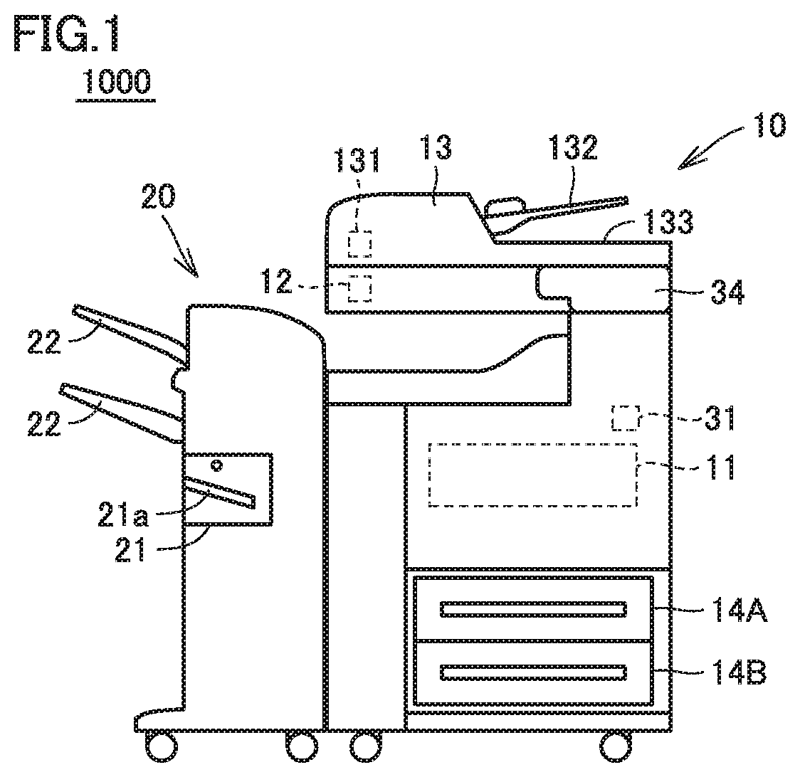
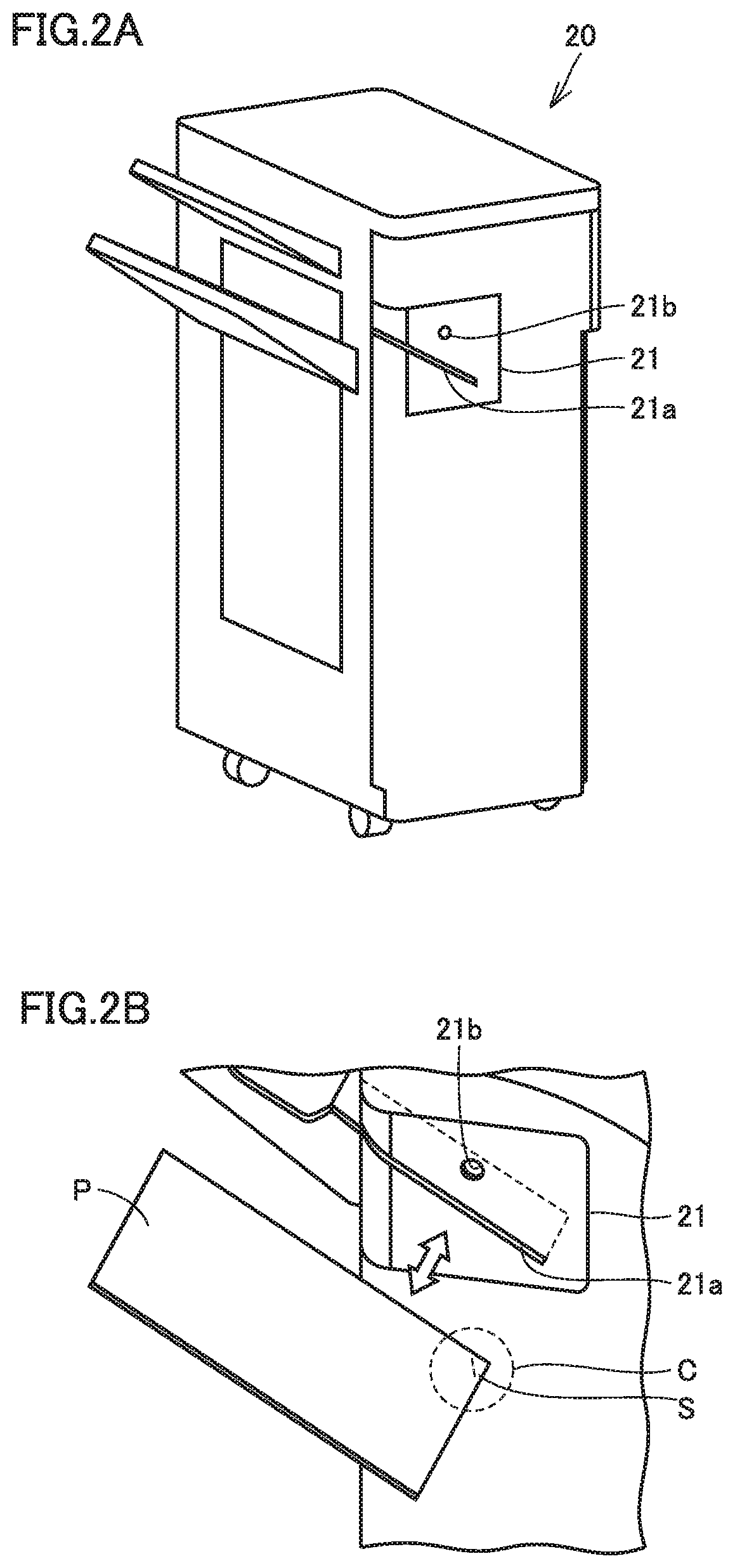
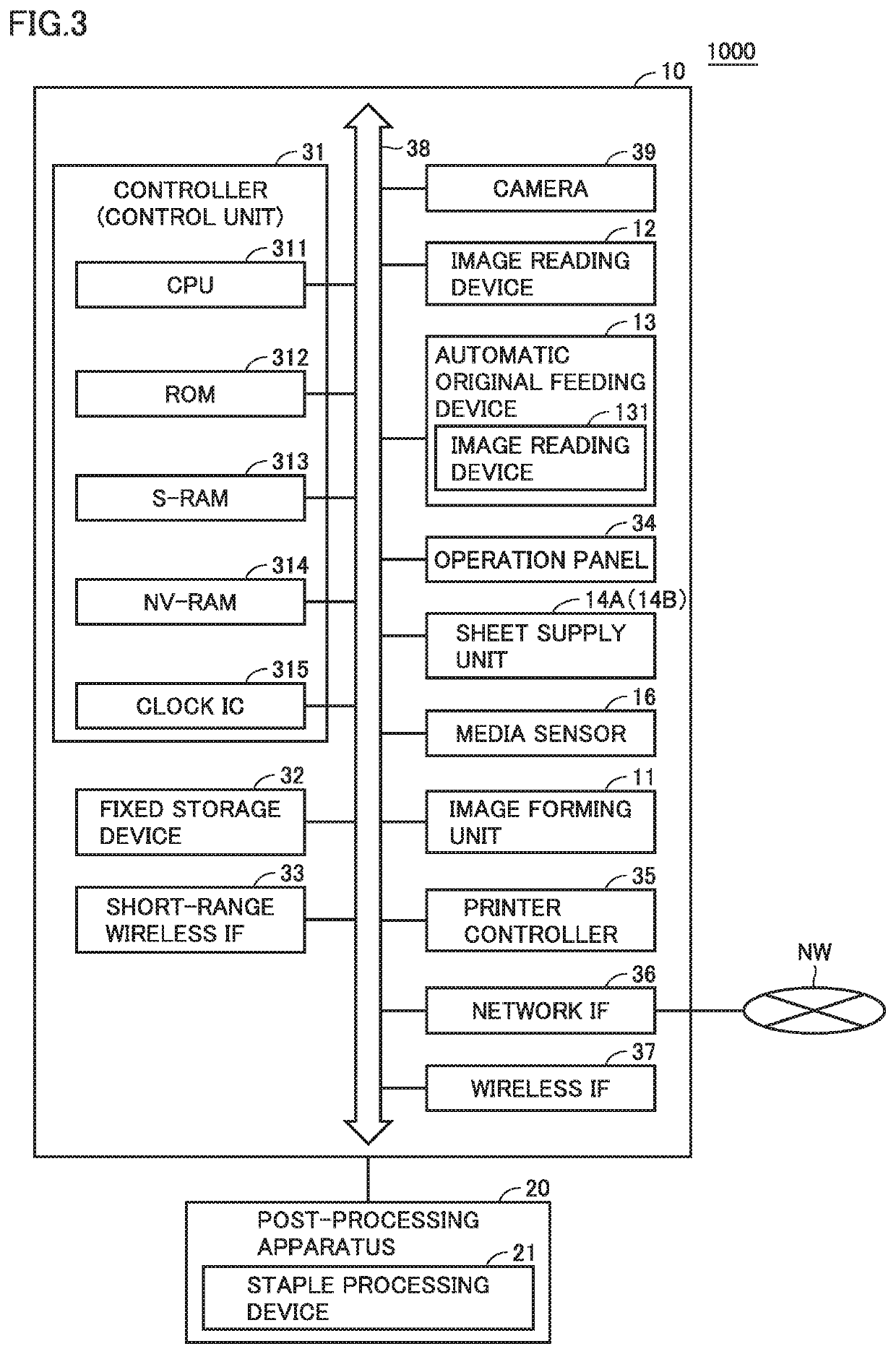
[0063]Hereinafter, one or more embodiments of the present disclosure will be described with reference to the drawings. However, the scope of the disclosure is not limited to the disclosed embodiments.

[0064]An image forming system in an embodiment will be described below with reference to the drawings. When the number, amount, or the like is referred to in the embodiment described below, the scope of the present disclosure is not necessarily limited to such a number, amount, or the like, unless otherwise specified. Identical or corresponding parts will be designated by the same reference numerals, and redundant description may not be repeated.

[0065]In the drawings, there are some parts that are not shown in accordance with the ratio of actual dimensions, but are shown with the ratio being changed to clarify a structure for easier understanding of the structure. It should be noted that variations described below may be selectively combined as appropriate.

[0066]In the following, a conf...


PUM


Abstract

An image forming system includes an image forming apparatus having an image reading device, and a post-processing apparatus having a manual staple mechanism. The manual staple mechanism is capable of performing staple processing on condition that power is supplied from the image forming apparatus to the post-processing apparatus. The image forming apparatus stops power supply to the post-processing apparatus on condition that a predetermined time has elapsed since reference timing. When the image forming apparatus reads an original with the image reading device, the image forming apparatus determines presence or absence of a staple mark in the original based on a read result. When the image forming apparatus determines that the staple mark is present, the image forming apparatus extends the predetermined time.

Description

[0001]The entire disclosure of Japanese Patent Application No. 2019-095929, filed on May 22, 2019, is incorporated herein by reference in its entirety.BACKGROUNDTechnological Field[0002]The present disclosure relates to an image forming system, a method for controlling power supply, and a computer-readable recording medium capable of performing manual staple processing.Description of the Related Art[0003]Conventionally, image forming apparatuses such as a printer, a copying machine, a facsimile, and a multi-functional peripheral thereof have been known. To such an image forming apparatus, a post-processing apparatus can be connected, which performs staple processing and the like on sheets subjected to image formation.[0004]There are two types of staple processing: one is auto staple processing that automatically staples a plurality of ejected sheets in the post-processing apparatus when a user provides an instruction beforehand, and the other is manual staple processing that staples...

Claims


Application Information

Patent Timeline
IPC IPC(8): H04N1/00
CPCH04N1/00639H04N1/00602H04N1/00896H04N1/00904Y02D10/00
Inventor HIBINO, TAKESHIYAMAHATA, TAKETOSHI
Owner KONICA MINOLTA INC
Learn More