
Spine regularity rotation motion device

a motion device and spine technology, applied in the field of spine regularity rotation motion devices, can solve the problems of pain or soreness, inability to easily observe and sometimes overlook slight deformations, and long-term pain of the body, so as to speed up the redressing process, and loosen the spine joints

Active Publication Date: 2022-02-15
KAO JUI TING
View PDF22 Cites 1 Cited by
  • Summary
  • Abstract
  • Description
  • Claims
  • Application Information

AI Technical Summary

Benefits of technology

The present invention is a lumbar rotation device that allows users to adjust and traction themselves for rehabilitation or to render operations unnecessary. It can be controlled manually or through a computer program to accommodate different needs and symptoms. The device helps user achieve safe rehabilitation and correction of cervical and lumbar spine by pulling from potentially different directions and angles. It also includes high-speed vertical vibration to help loosen spine joints and speed up the redressing process.

Problems solved by technology

When the axis is deformed, the person may experience pain or soreness.
Slight deformation may not be easily observed and can sometimes be overlooked.
If the real cause of a discomfort is not identified, the body may be suffering from long-term pain, soreness or numbness.

Method used


Image

  • Spine regularity rotation motion device
  • Spine regularity rotation motion device
  • Spine regularity rotation motion device

Examples


first embodiment

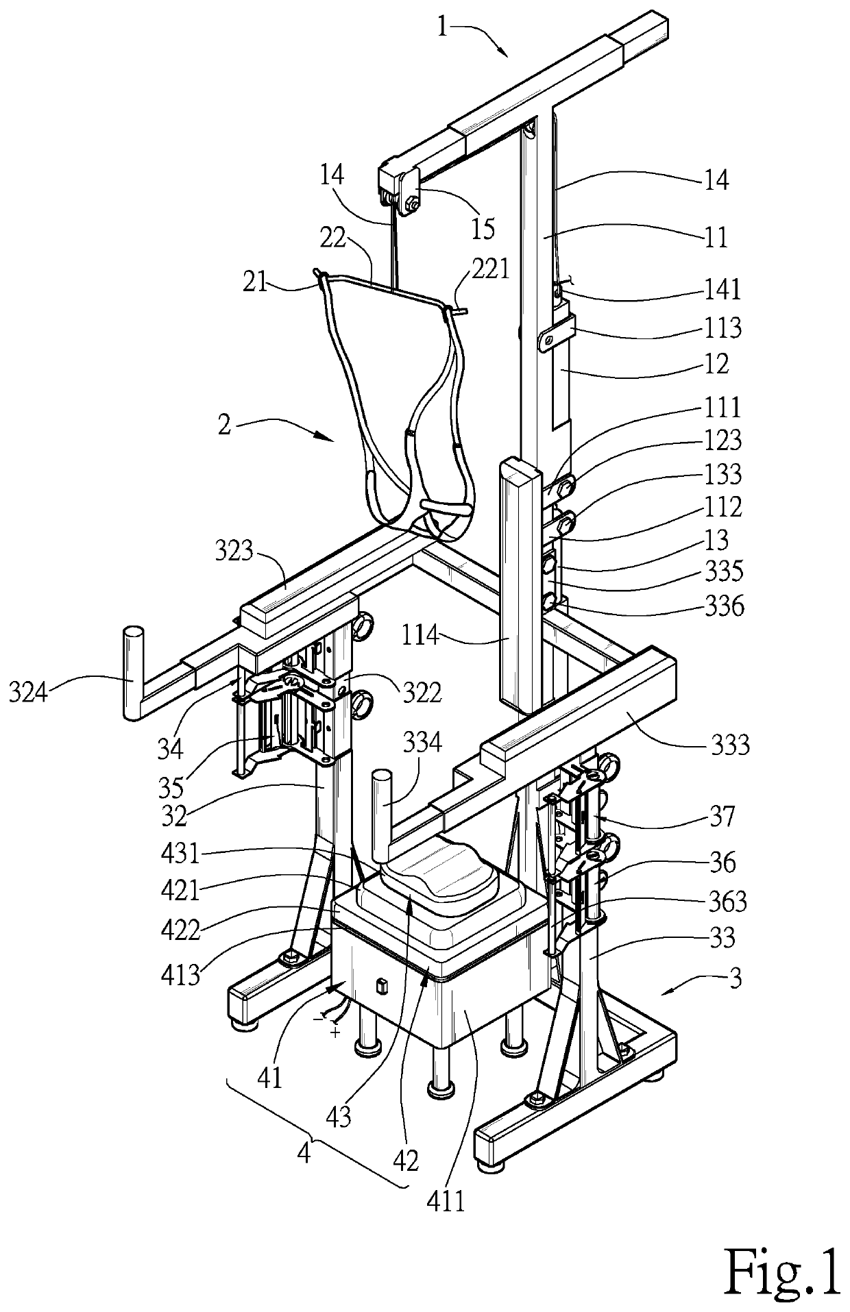
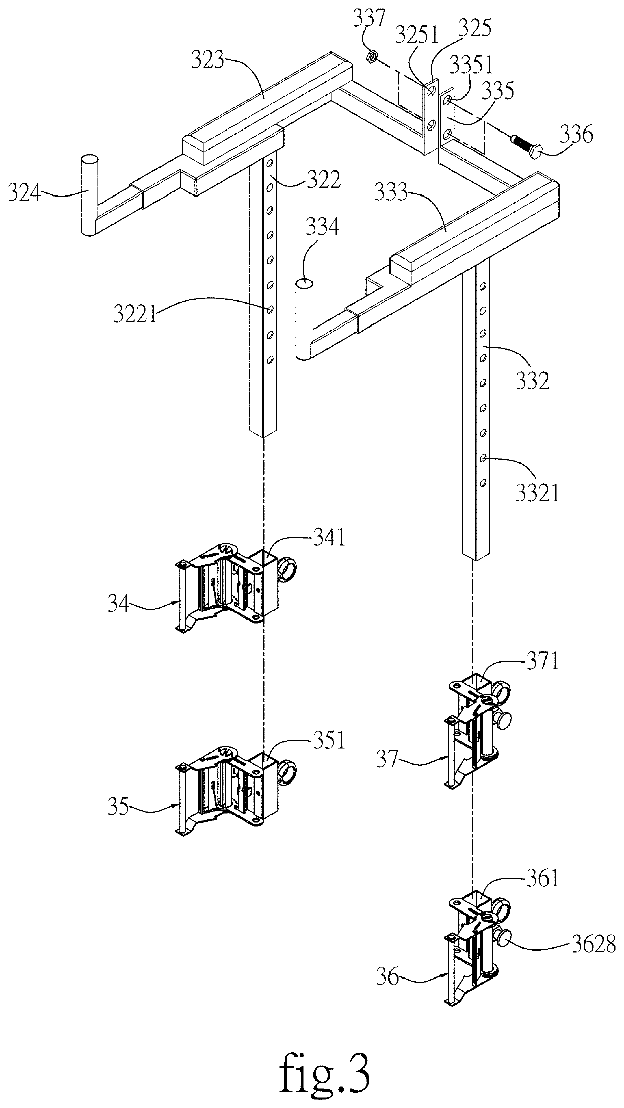
[0054]Referring to FIGS. 9, 12, 12-1 and 12-2, a schematic view of the correction seat of the present invention, a back view of the correction seat in use, a partially enlarged view of section A of FIG. 12 showing a first regularity rotation motion pattern of the lumbar spine, and a partially enlarged view of section A of FIG. 12 showing a second regularity rotation motion pattern of the lumbar spine are shown, respectively. As can be seen from the drawings, a user rests his arms on the left and right handle pads 333 and 323, which can be adjusted according to the height of the user. Ideally, the arms are lifted slightly to raise the spine and reduce stacking, such that there is no gravity oppression from the scapula to the pelvis of the lumbar spine in order to facilitate returning the spine to its correct place. The horizontal rotary drive platform 4 allows the pelvis to swing left or right regularly at 10˜60 times per minute. For example, if the spine is twisted, then the curved ...

second embodiment

[0055]As shown in FIGS. 13, 14, 14-1 and 14-2, a schematic view of the correction seat of the present invention, a back view of the correction seat in use, a partially enlarged view of section B of FIG. 14 showing a third regularity rotation motion pattern of the lumbar spine, and a partially enlarged view of section B of FIG. 14 showing a fourth regularity rotation motion pattern of the lumbar spine are shown, respectively. The horizontal rotary drive platform 4 allows the pelvis to rotate along an S shape regularly at 10˜60 times per minute. For example, if the lumbar spine is bent and twisted, then the balance disk 432 can be used. As shown in FIG. 14-1, for a patient with the lumbar spine twisted and bent to the right (shown by arrows PRI), the balance disk 432 is turned clockwise and in opposite direction to the bent lumbar spine. In FIG. 14-2, for a patient with the lumbar spine twisted and bent to the left (shown by arrows PLI), the balance disk 432 is turned anti-clockwise a...

third embodiment

[0056]As shown in FIGS. 15, 16, 16-1 and 16-2, a schematic view of the correction seat of the present invention, a back view of the correction seat in use, a partially enlarged view of section C of FIG. 16 showing a fifth rhythmic motion pattern of the lumbar spine, and a partially enlarged view of section C of FIG. 16 showing a sixth regularity rotation motion pattern of the lumbar spine are shown, respectively. The horizontal rotary drive platform 4 allows the pelvis to rotate in an S shape regularly at 10˜60 times per minute. For example, if the pelvis is skew, then the balance ball 433 can be used. As shown in FIG. 16-1, for a patient with part of the spine bent to the right (shown by arrows PRS), the balance ball 433 is turned clockwise and in opposite direction and angle to the bent spine. In FIG. 16-2, for a patient with part of the spine bent to the left (shown by arrows PLS), the balance ball 433 is turned anticlockwise and in opposite direction and angle to the bent lumbar...


PUM


Abstract

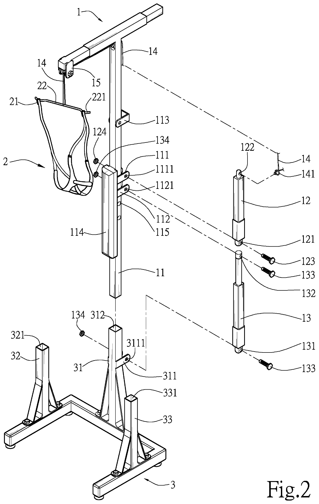
A spine regularity rotation motion device includes a T-shaped hanger, a neck traction belt, an n-shaped base, and a horizontal rotary drive platform, wherein the T-shaped hanger is connected to the neck traction belt via a pulling belt at one end, and is connected to the n-shaped base through a main elevating post at another end. A user can rest his face on the neck traction belt, which is gently pulled upwards to increase the space between the cervical joints and align the spine to the center. The horizontal rotary drive platform is provided inside the n-shaped base with a correction seat on the top for the user to sit on. The seat allows the hip of the user to move in a regularity rotation manner that is opposite to the directions of the twisted and / or bent lumbar spine or skewed pelvis. An underarm support is also provided to raise the spine and reduce stacking to facilitate the rehabilitation process.

Description

BACKGROUND OF THE INVENTION1. Field of the Invention[0001]The invention relates to a regularity rotation motion device applicable to lumbar physiotherapy, and more particularly, to a lumbar regularity rotation motion device capable of redressing the lumbar spine to its correct angle or location.2. Description of the Prior Art[0002]The skeletal system of the human body is like steel bars that support a building. The skeletal system is like a “skeleton axis”; the head is like the roof, and the pelvis is like the foundation. When the axis is deformed, the person may experience pain or soreness. More severe deformation in the “skeletal axis” may be physically visible, for example, symptoms like one side of the shoulders being higher than the other side, Thoracic scoliosis, waist bending, humpback, pelvic skew, hip overturned or excessively flat etc. may be observed. Slight deformation may not be easily observed and can sometimes be overlooked. If the real cause of a discomfort is not id...

Claims


Application Information

Patent Timeline
Patent Type & Authority Patents(United States)
IPC IPC(8): A61H1/02A61H1/00
CPCA61H1/0296A61H1/005A61H1/0229A61H2201/0176A61H2201/1215A61H2201/1652A61H2203/0431A61F5/0104A61F5/042A61H1/008A61H1/0218A61H1/0292A61H2201/1207A61H2205/04A61H2205/081A61H2201/1633A61H2201/1664A61H23/02A61H2201/1611
Inventor KAO, JUI-TING
Owner KAO JUI TING
Learn More