Vibrational densification of powder supply in additive manufacturing

a powder supply and additive manufacturing technology, applied in the direction of additive manufacturing, additive manufacturing processes, applying layer means, etc., can solve the problem of material becoming more compact, and achieve the effect of improving the quality of the object being made, more compacting, and robust additive manufacturing process

Active Publication Date: 2022-02-22
EOS ELECTRO OPTICAL SYST
View PDF9 Cites 0 Cited by
  • Summary
  • Abstract
  • Description
  • Claims
  • Application Information

AI Technical Summary

Benefits of technology

[0005]It is a principal object of the present invention to provide an apparatus and method for densifying, or compacting, the powder material in the supply bin of an additive manufacture machine and process, to thereby improve the quality of the object being made and / or to make the additive manufacturing process more robust and / or more effective. In one preferred form, the invention is a removable or portable apparatus which is applied to the surface or the inner side of the supply bin once the bin has been filled, or at least partially filled; in the latter case, the bin can be filled in a stepwise manner, i.e. involving more than just one step of filling the supply bin with powder but rather several sub-steps of filling part of the overall powder amount with more than one compaction or densification step in between. The apparatus has a vibrational component which agitates the underlying powder, causing the material to become more compacted. The apparatus is then removed for the additive manufacture process which then follows in its normal course. A vacuum or suction is furthermore advantageously applied during operation of the apparatus, to facilitate the removal of air or other gases which are outgassed during the compaction process (as previous voids are filled in densification).

Problems solved by technology

The apparatus has a vibrational component which agitates the underlying powder, causing the material to become more compacted.

Method used


Image

  • Vibrational densification of powder supply in additive manufacturing
  • Vibrational densification of powder supply in additive manufacturing
  • Vibrational densification of powder supply in additive manufacturing

Examples


Embodiment Construction

[0019]While this invention is susceptible of embodiments in many different forms, there is shown in the drawings, and will herein be described in detail, a preferred embodiment of the invention with the understanding that the present disclosure is to be considered as an exemplification of the principles of the invention and is not intended to limit the broad aspect of the invention to embodiments illustrated. As used herein, the term “present invention” is not intended to limit the scope of the claimed invention and is instead a term used to discuss exemplary embodiments of the invention for explanatory purposes only.

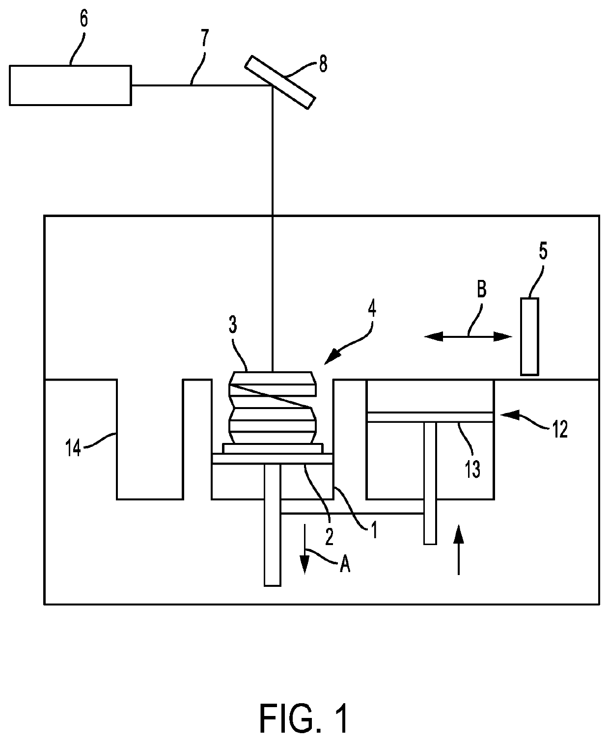
[0020]FIG. 1 shows a laser sintering apparatus as an exemplary embodiment of an apparatus in the context of an aspect of the invention. The laser sintering apparatus comprises a container or build chamber 1 that is open towards the top. A support 2 for carrying the object 3 to be built is provided in the build chamber 1. The support 2 can be moved up and down (typically...


PUM

PropertyMeasurementUnit
surface areaaaaaaaaaaa
lengthaaaaaaaaaa
manual movementaaaaaaaaaa

Abstract

Disclosed are an apparatus and method for densifying or compacting powder material in the supply bin of an additive manufacture machine to improve the quality of the object being made. For example, a removable or portable apparatus can be applied to the surface of the supply bin once the bin has been filled. The apparatus can include a vibrational component that agitates the underlying powder to compact the material. The apparatus can then be removed during the remainder of the additive manufacturing process, which then follows in its normal course. A vacuum can also be used the remove of air or other gases that are emitted during the compaction process, for example, as voids are filled during densification.

Description

TECHNICAL FIELD OF THE INVENTION[0001]The invention relates to an apparatus and method for use in densifying, or compacting, a powder supply in a layer-wise manufacture of a three-dimensional object.BACKGROUND OF THE DISCLOSURE[0002]More and more, additive manufacturing machines and methods are used not only for the making of prototypes, but for the manufacture of usable products, whether in small series manufacture or in the production of large volume commercial parts. A very important aspect in the production is the manufacturing time, as well as the quality of the part produced. A “finer” detail finished object yields a better quality, particularly in additive manufacture using powder build material. However, usually a manufacturing time that is as short as possible is at the expense of object details that are as small as possible.[0003]Additive manufacturing, sometimes referred to short-hand as “3D printing,” is now well known in general concept and execution. In a layer-wise pr...

Claims


Application Information

Patent Timeline
Patent Type & Authority Patents(United States)
IPC IPC(8): B22F3/093B33Y30/00B33Y40/00B33Y10/00B22F3/00B29C64/205B29C64/153B22F12/00B22F10/10
CPCB22F3/093B22F3/004B29C64/205B33Y10/00B33Y30/00B33Y40/00B22F10/10B22F12/00B22F2999/00B29C64/153Y02P10/25B22F12/50B22F10/28B22F2202/01B22F2201/20
Inventor SAHARAN, III, ANKITLASALLE, ERLING RICHARD
Owner EOS ELECTRO OPTICAL SYST
Why Eureka
Try Eureka