
Installation tool for clamping rings

a technology for installing tools and clamping rings, applied in the field of power tools, can solve the problems of affecting the the installation tool of the the installation tool of the known pneumatically controlled controller is not maintenance free, etc., to achieve the effect of reducing and/or eliminating maintenance problems, reducing and not excessively imposing force, and smooth operation of the installation tool

Active Publication Date: 2022-03-15
SPAZZADESCHI ILARIO GIUSEPPE +2
View PDF4 Cites 0 Cited by
  • Summary
  • Abstract
  • Description
  • Claims
  • Application Information

AI Technical Summary

Benefits of technology

This invention is an installation tool that eliminates the need for manual clamping of clips and provides a precise and smooth operation. The tool is powered by an electric motor and is controlled by an electronic control unit to ensure precision in its operation. Additionally, the tool is designed to be easily handled with a grip housing and is designed to clamp clips in hard-to-reach places. These technical effects reduce maintenance issues and provide a more efficient and effective installation tool.

Problems solved by technology

However, the pneumatically controller installation tools also tend to have various disadvantages and limitations associated with them.
Moreover, the available state of technology in the pneumatically controller installation tools exhibits strong dispersions of the compression forces as it generally fails to not maintain its compression force at a constant pressure and they lose their compression force during the serviceable life due to which non-precise closing position may be reached, thereby defaulting the assembly or installations.
Another disadvantage lies in the fact that the known pneumatically controller installation tools may not be maintenance free.

Method used


Image

  • Installation tool for clamping rings
  • Installation tool for clamping rings
  • Installation tool for clamping rings

Examples


Embodiment Construction

[0031]For a thorough understanding of the present invention, reference is to be made to the following detailed description, including the appended claims, in connection with the above-described drawings. Although the present invention is described in connection with exemplary embodiments, the present invention is not intended to be limited to the specific forms set forth herein. It is understood that various omissions and substitutions of equivalents are contemplated as circumstances may suggest or render expedient, but these are intended to cover the application or implementation without departing from the spirit or scope of the claims of the present invention. Also, it is to be understood that the phraseology and terminology used herein is for the purpose of description and should not be regarded as limiting. The use of “including,”“comprising,” or “having” and variations thereof herein is meant to encompass the items listed thereafter and equivalents thereof as well as additional...


PUM


Abstract

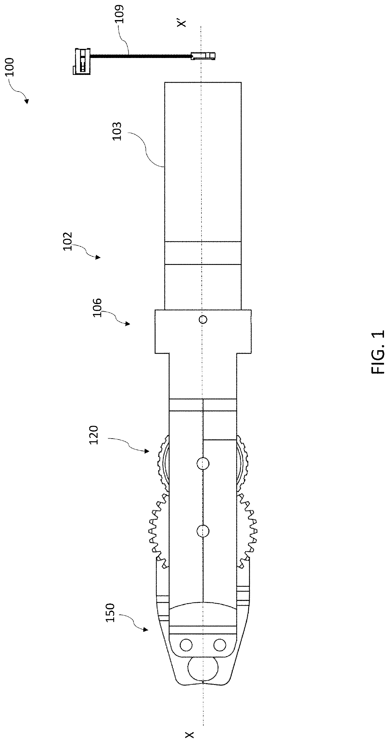
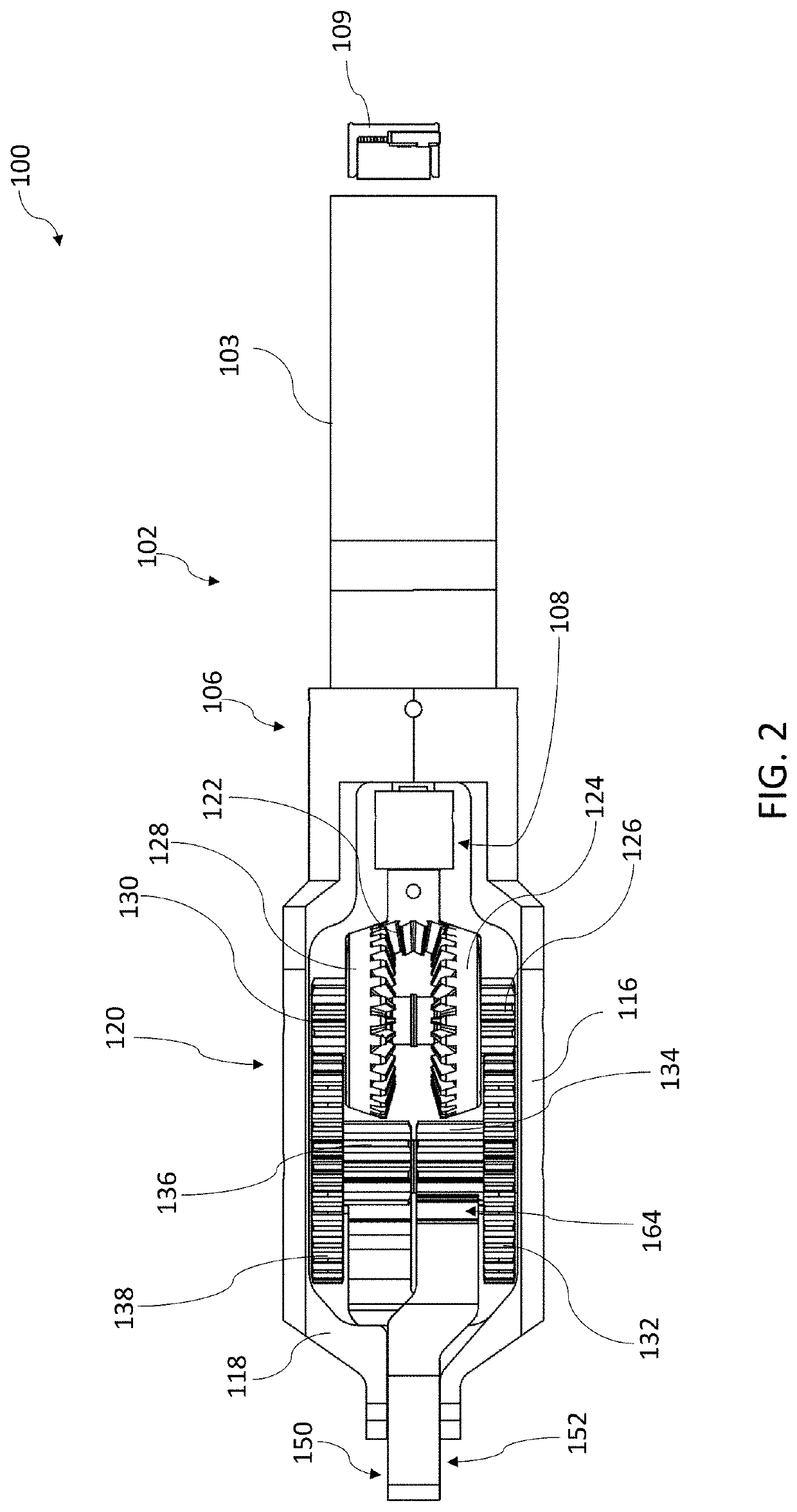
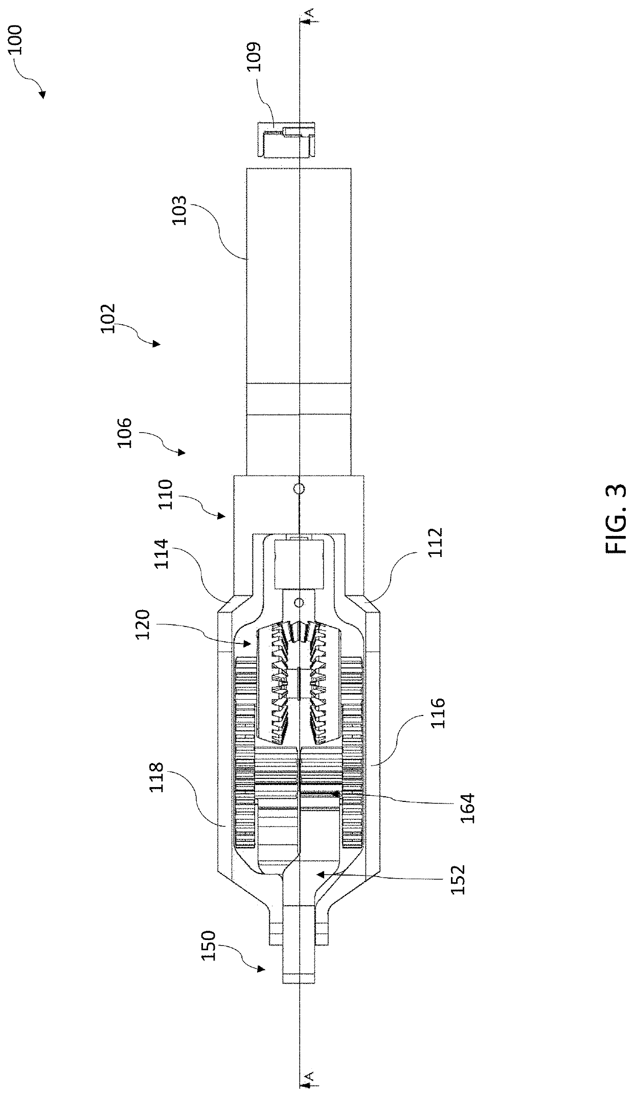
An installation tool for installing and uninstalling lock rings, bolts, cable lugs, hose clamps is provided. The installation tool comprises a frame assembly and a driving member secured to the frame assembly. The installation tool also comprises a gear assembly operatively coupled to the frame assembly. The gear assembly comprises a plurality of gears which are configured to receive rotational input from the driving member. The installation tool further comprises a jaw assembly operatively coupled to the gear assembly and the frame assembly. The jaw assembly comprises a plurality of jaw members which are configured to receive rotational input from the gear assembly. The installation tool comprises an electronic control unit and an intuitive graphic interface having a touch display. The installation tool ensures precise closing position of the jaw assembly to the tenth of a millimeter.

Description

CROSS REFERENCE TO RELATED APPLICATIONS[0001]The present invention claims priority under 35 United States Code, Section 119 on the provisional application No. 62 / 735,264 filed on Sep. 24, 2018, the disclosure of which is incorporated by reference.FIELD OF THE INVENTION[0002]The present invention generally relates power tools, and, more particularly, to a tool for installation or manipulation of clamping rings, locking rings, bolts, cable lugs, and hose clamps etc.BACKGROUND OF THE INVENTION[0003]Fastening elements, such as locking rings, bolts, cable lugs, hose clamps etc., are used in various fields and applications. For example, in automotive industry clamping rings are used for fixing flexible hoses on ridged nipples or for fastening bellows on universal shafts. Among other things, one of the most important factors that are required for successful installation of such clamping rings over the flexible hoses is whether or not the clamping rings are tightened with sufficient, but no...

Claims


Application Information

Patent Timeline
Patent Type & Authority Patents(United States)
IPC IPC(8): B25B25/00
CPCB25B25/005B25B27/146H01R43/0428
Inventor SPAZZADESCHI, ILARIOSPAZZADESCHI, ENRICOSPAZZADESCHI, RICCARDO
Owner SPAZZADESCHI ILARIO GIUSEPPE
Learn More