Motor component for a linear motor

a linear motor and motor component technology, applied in the direction of propulsion systems, magnetic circuit shapes/forms/construction, cooling/ventilation arrangements, etc., can solve the problems of complex, unfavorable economic development, and comparatively voluminous motors of this typ

Active Publication Date: 2022-03-15
KESSLER ENERGY GMBH
View PDF5 Cites 0 Cited by
  • Summary
  • Abstract
  • Description
  • Claims
  • Application Information

AI Technical Summary

Benefits of technology

[0009]With the aid of the motor component according to the present invention for a linear motor, it is made possible that considerably fewer components are required. The linear motor or the motor component can also be of substantially smaller or more compact construction and can additionally be produced and operated less expensively in comparison with the prior art with an approximately identical drive power or propulsive force. In addition, synergetic effects can be utilized in the case of the energy and / or heat management, with the result that a more energy-efficient mode of operation can be realized.
[0031]In conjunction with one advantageous embodiment, in the case of which the cooling ducts are let into the cooling element, it has already been explained that this open region of the cooling ducts should be covered, which can take place, for example, with the aid of a cover and / or sealing element, in particular, a sealing ring. When, above all, the cooling element itself is manufactured from aluminum, the cover can advantageously likewise be manufactured from aluminum, which has the advantage, inter alia, that the cover and the cooling element therefore have the same or at least a very similar coefficient of thermal expansion in the case of heating, and accordingly both also behave identically in the case of identical heating and mechanical stresses do not occur. A cover represents an inexpensive variant for covering and for closing the entirety of the cooling ducts, a rubber ring or the like preferably being used as seal.

Problems solved by technology

It is disadvantageous here, however, that motors of this type are comparatively voluminous, complex and economically unfavorable.

Method used


Image

  • Motor component for a linear motor
  • Motor component for a linear motor
  • Motor component for a linear motor

Examples


Embodiment Construction

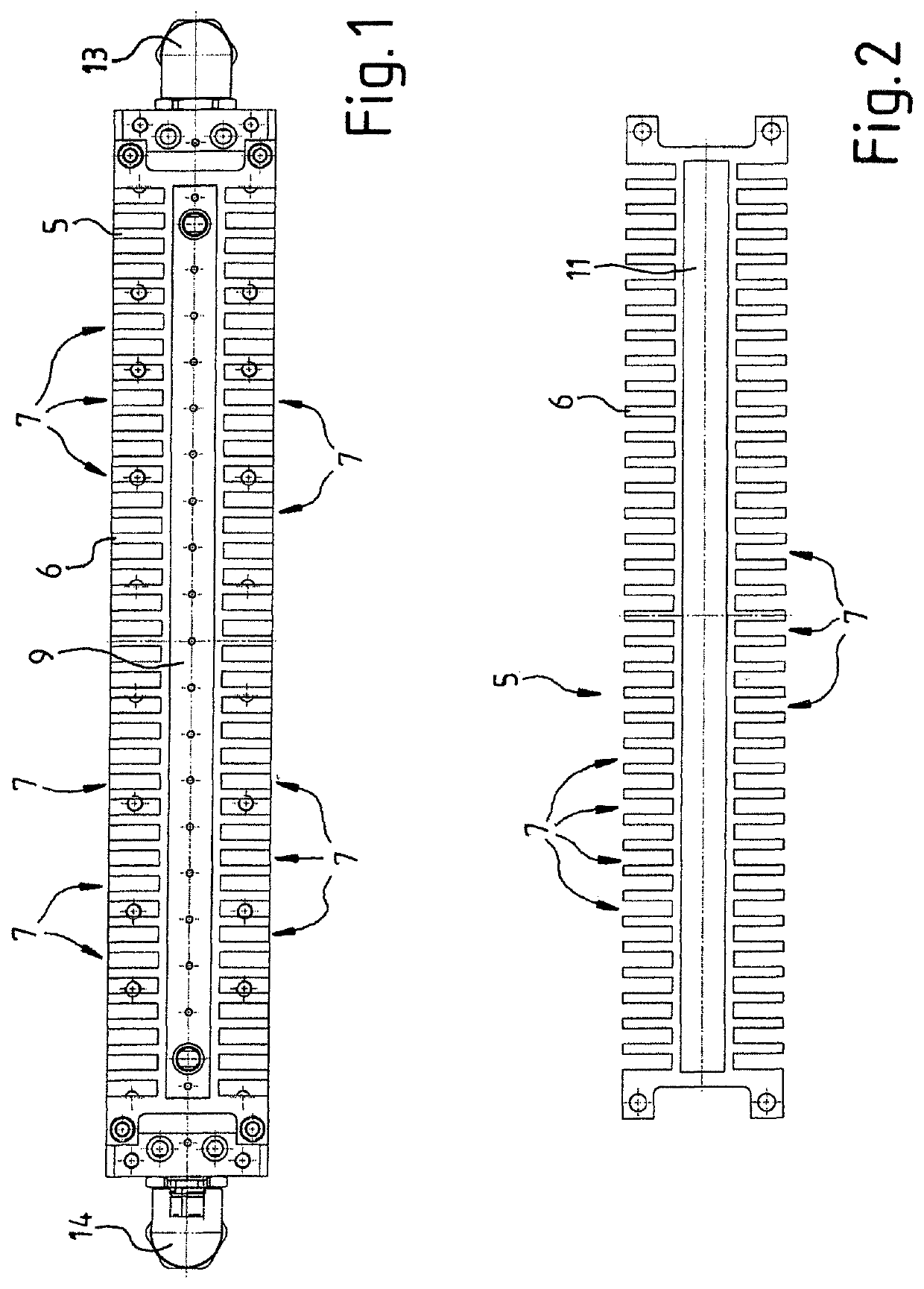
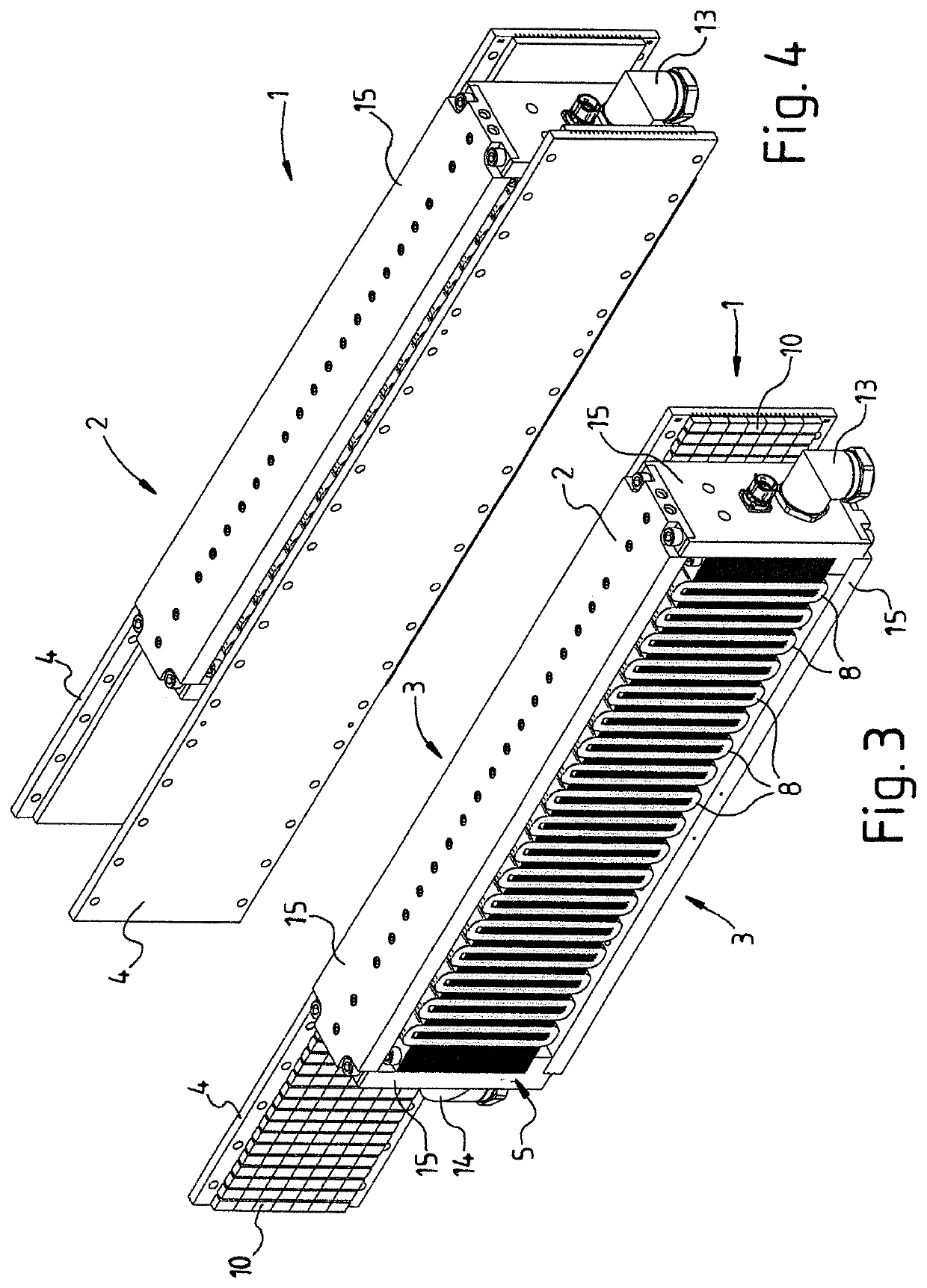
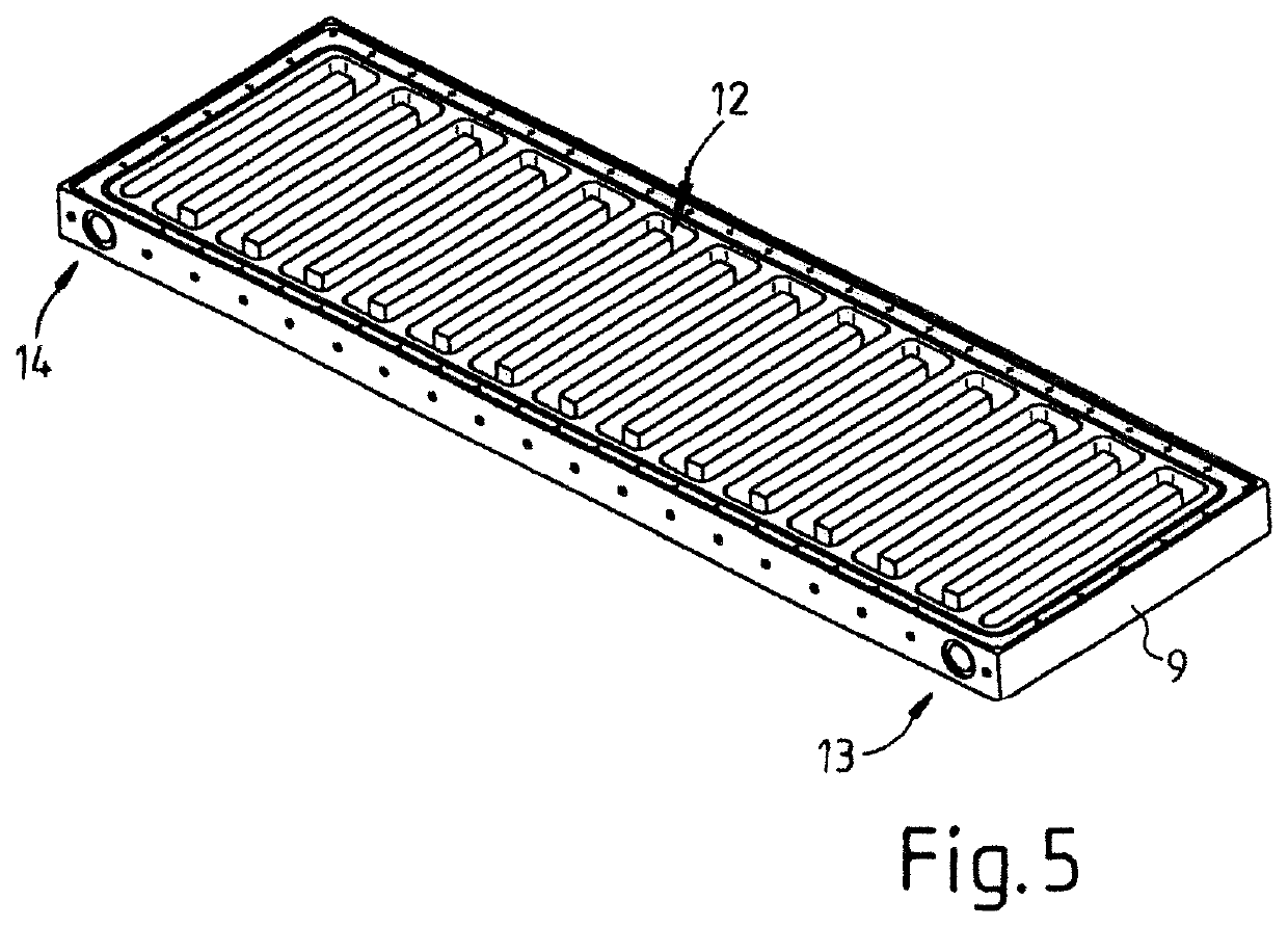
[0042]The figures diagrammatically show a motor component 2 for a linear motor 1 having two primary parts 3 and two secondary parts 4 which are fitted with permanent magnets 10. According to the present invention, the motor component 2 for a linear motor 1 comprises a laminated core 5 which is assembled from numerous single-piece laminations 6. In advantageous recesses 7 or grooves 7 on a first longitudinal side, the laminations 6 or the laminated core 5 receive / receives first coils 8 for a first primary part 3 and, in advantageous recesses 7 or grooves 7 on a second longitudinal side, receive / receives second coils 8 for a second primary part 3. This means that, as illustrated in FIG. 4, in particular, the two primary parts 3 with the coils 8 are arranged between two secondary parts 4. The motor component 2 is configured as a single-piece structural unit 2 and additionally comprises the laminated core 5 according to the present invention. Moreover, very stable / rigid frame 15 of the ...


PUM


Abstract

A motor component for a linear motor having a first primary part with two first electromagnetic coils and a second primary part with two second electromagnetic coils, arranged substantially parallel in relation to one another. At least one common laminated core unit is provided for the first and the second primary parts, which common laminated core unit comprises one-piece sheet-metal elements. Each of the one-piece sheet-metal elements of the laminated core unit in each case has first recesses, which are arranged one behind the other in the longitudinal direction of an adjustment path of the linear motor, for the first coils of the first primary part and at second recesses, which are arranged one behind the other in the longitudinal direction of the adjustment path of the linear motor, for the second coils of the second primary part.

Description

CROSS REFERENCE TO RELATED APPLICATIONS[0001]This application is a continuation of International Application No. PCT / EP2017 / 073952 filed Sep. 21, 2017, which designated the United States, the entirety of which is incorporated herein by reference.FIELD OF THE INVENTION[0002]The present invention relates to a motor component for a linear motor and to a linear motor.BACKGROUND OF THE INVENTION[0003]A very wide variety of linear motors are already commercially available. Their increasing importance in mechanical engineering and plant engineering is due, inter alia, to the high accelerations and speeds which can be realized, and also to their high positioning accuracy and long adjusting travels which can be realized.[0004]Linear motors usually comprise at least one so-called primary part, a plurality of coils, through which current flows, generating a variable and / or controllable magnetic field, and at least one so-called secondary part which has a multiplicity of permanent magnets. The ...

Claims


Application Information

Patent Timeline
Patent Type & Authority Patents(United States)
IPC IPC(8): H02K41/02H02K41/035H02K9/197
CPCH02K41/0356H02K9/197H02K2201/09H02K41/031H02K1/20H02K5/203
Inventor TROLLIET, PATRICKSINNER, MARKUS
Owner KESSLER ENERGY GMBH
Why Eureka
Try Eureka