Vehicular frame's coupler structure

a coupler and bicycle technology, applied in the direction of bicycles, cycle frames, bicycle equipment, etc., can solve the problems of high production cost, large frame of bicycles, difficult economic transportation, etc., and achieve the effect of reducing manufacturing costs

Active Publication Date: 2022-03-22
ALUMIS
View PDF7 Cites 0 Cited by
  • Summary
  • Abstract
  • Description
  • Claims
  • Application Information

AI Technical Summary

Benefits of technology

[0009]It is an objective of the present invention to provide a vehicle frame having multiple frame components that connect to one another to form one assembled vehicle, such as a bicycle. By design, two inner faces of the connection parts (front and rear, respectively) have an inclined angle that allows the coupler to be well-fitted together. By inserting and fastening the coupler bolts into the left and right sides, the two frames are securely connected. The two inclined inner surfaces are designed to interact with each other to prevent slippage and strengthen the overall cohesiveness of the coupler. By having this type of special design, the coupler part is strengthened to prevent separation during use.
[0010]It is another objective of the present invention to provide a vehicle frame having two frames securely fastened together, and even though this vehicle was constructed from multiple parts, the vehicle is able to stay stable while being operated on. With the simplicity of the coupler system, it is possible to reduce the manufacturing cost. Furthermore, because the inclined inner surfaces of the front and rear couplers are hidden from the user, they do not interfere with the rider's body, making the riding experience safe and enjoyable.
[0011]It is another objective of the present invention to provide a vehicle frame's coupler structure having a jagged part in the middle of the coupler that prevents the coupler from separating. Furthermore, there are pin holes in the inner surface of the coupler that further strengths the coupler from separation. The aforementioned jagged part and the pin holes not only prevents relative displacement, but also resists any relative rotation that may occur during use.
[0013]With the aforementioned objectives, the connection part between the two frames does not only resist relative rotation, but also increases the overall strength of the bicycle's frame system.
[0014]In some embodiments of the vehicle frame's coupler structure, the coupler is configured to accommodate several more bolts that are lined up in the same plane, next to each other. Simultaneously, with several bolts, it is possible to further increase the overall strength and hardness of the coupler frame.
[0016]This invention is the method in which multiple frames can be assembled into a final product. Because of the unique shapes and structure of the coupler, as well as the way the front and back frame fits together, the vehicle is not prone to sudden disassembly during use. Furthermore, the structure is designed to lower manufacture cost. After assembly of the bicycle, because the inner face of the coupler system is hidden from the rider, the user's clothes or body will not catch on or interact with the bicycle in any way as to interfere with the riding experience.

Problems solved by technology

However, the frame of a bicycle can be large and difficult to economically ship.
However, one of the problems with the design of the frame is the high production cost that comes with the complexity of the coupler component.

Method used


Image

  • Vehicular frame's coupler structure
  • Vehicular frame's coupler structure
  • Vehicular frame's coupler structure

Examples


Embodiment Construction

[0028]Reference is made herein to the attached drawings. Like reference numerals are used throughout the drawings to depict like or similar elements of the carrying case. For the purposes of presenting a brief and clear description of the present invention, the preferred embodiment will be discussed as used for a collapsed folding chair therein. The figures are intended for representative purposes only and should not be considered to be limiting in any respect.

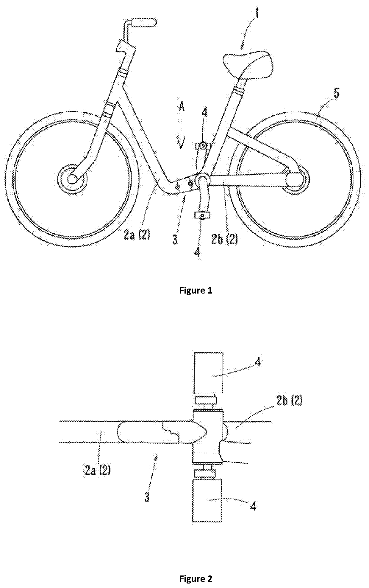
[0029]Referring now to FIGS. 1 and 2, there is shown a side view of an embodiment of the vehicle frame's coupler structure, wherein the vehicle is a bicycle and a close-up view of an embodiment of the vehicle frame's coupler structure, as seen from direction A of FIG. 1, respectively. In the illustrated embodiment, the vehicle is a bicycle having a frame 2 that is configured to be separated into two distinct parts, a front frame 2a and a back frame 2b. The vehicle frame's coupler structure 3 connects the front frame 2a to the ...


PUM


Abstract

A vehicle frame's coupler structure that connects separable frames for easy assembly and disassembly, at a low cost. Further, the couple structure can provide a vehicle that is easy to operate, without affecting the user when in use. The vehicle frame's coupler structure includes combining a Front-side Coupler Inner Face (8) with Rear-side Coupler Inner Face (9), and after making sure all components of (8) and (9) are in place (no protruding edges, etc.), and using Bolt (15) to fasten Part (6) with Part (7). The end result is the coupler system of the vehicle.

Description

CROSS REFERENCE TO RELATED APPLICATION[0001]This application claims the benefit of JP utility patent application No. 2018-186371 filed on Oct. 1, 2018, the above identified patent application is herein incorporated by reference in its entirety.BACKGROUND OF THE INVENTION[0002]The present invention uses a special interlocking mechanism, which allows a bicycle to be assembled and disassembled into different parts.[0003]Due to increased use of bicycles and similar vehicles, there is an increased demand for manufactures to ship these bicycles across the world. However, the frame of a bicycle can be large and difficult to economically ship. Therefore, there is a need to provide frames capable of disassembling into multiple parts in order to save space for storage or during shipment. When the vehicle is not in use, various parts could be disassembled, neatly packaged in the original box for easy storage or shipping. Whether it be showcasing in a store or for everyday use, the present inve...

Claims


Application Information

Patent Timeline
Patent Type & Authority Patents(United States)
IPC IPC(8): B62K15/00B62K3/02
CPCB62K15/00B62K3/02B62K2015/001B62K3/06B62K19/24
Inventor TOMOHIKO, YODA
Owner ALUMIS
Why Eureka
Try Eureka