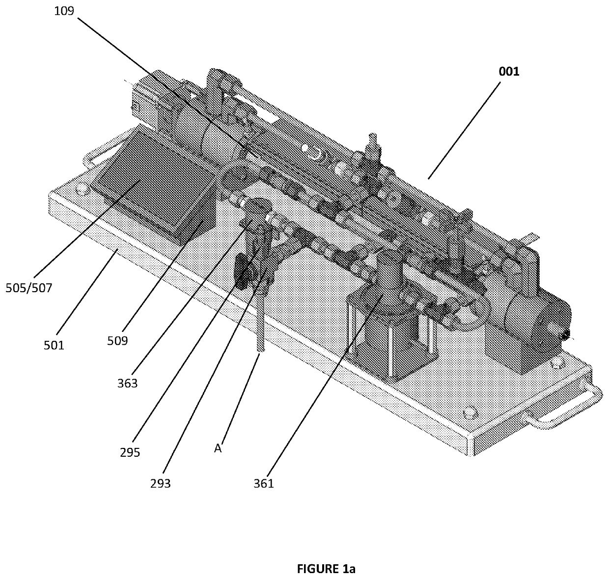
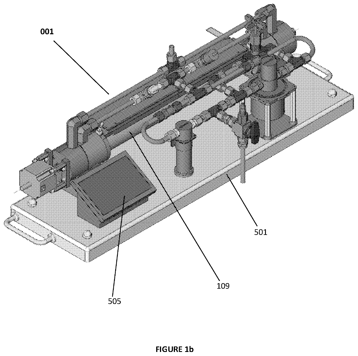
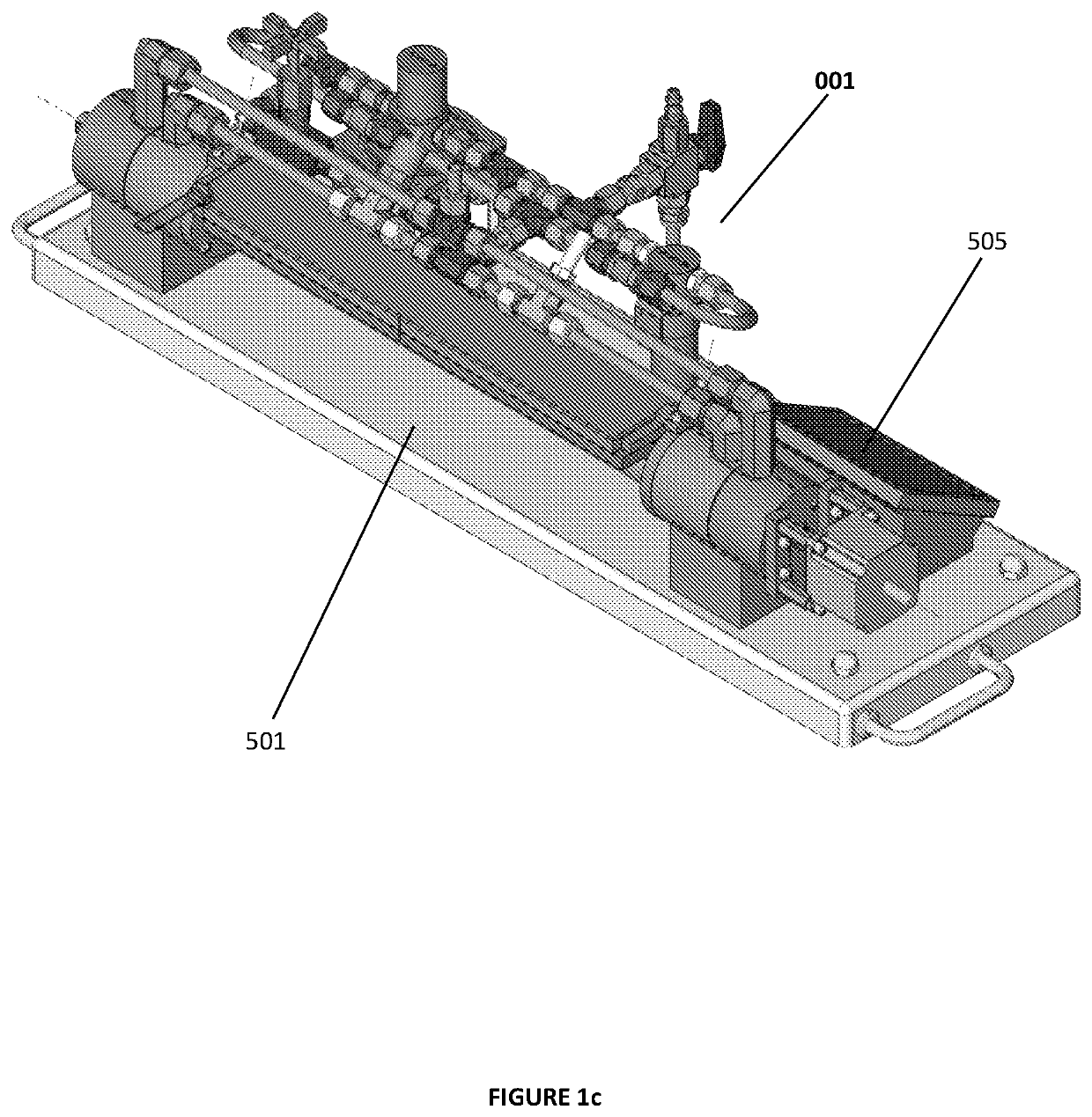
Reciprocating piston pump

a piston pump and reciprocating technology, applied in the direction of pump parameters, positive displacement liquid engine, instruments, etc., can solve the problems of shortening the life of equipment downstream of the pump, affecting the reliability of the pump, vibration and noise, etc., to achieve more reliable and accurate

Active Publication Date: 2022-03-22
QUANTA IQ INC
View PDF29 Cites 1 Cited by
  • Summary
  • Abstract
  • Description
  • Claims
  • Application Information

AI Technical Summary

Benefits of technology

[0018]Because the inventive subject matter measures flow through the displacement of a solid object, the need to replace the flexible rubber diaphragm is eliminated. A further advantage is that the piston is not as susceptible to chemical degradation as the diaphragm, as the material in question does not require it to flex. This advantage greatly reduces the frequency with which maintenance must be performed, increasing its reliability, and decreasing customer cost.
[0020]The accuracy and repeatability of the flow rates and volumes produced by the pump described herein are measurably better than that of a diaphragm dosing pump. This is the result of tracking a solid object, as opposed to displacing a flexible diaphragm over a specific distance to produce a scheduled rate of flow.
[0044]The reciprocating piston pump in the present application can precisely track piston position using a linear encoder.
[0045]The solid pushrod ensures that the valves inside of either endcap switch at the same time, in perfect unison with one and other. The use of a solid pushrod, as opposed to a pushrod which actuates individual spring-loaded valves through a lever, as the Hippen device does, eliminates numerous parts, and makes the device significantly more reliable and accurate.
[0046]4) Simplicity—The reciprocating piston pump herein contains only three moving parts, the PRV (pushrod valve assembly), the piston, and the encoder target housing. This limited number of moving parts ensures the reciprocating piston pumps reliability, and in turn its accuracy.

Problems solved by technology

This pulsation, which is a byproduct of the general design, produces vibration and noise.
In some applications, the pulsation produced by the pump leads to inaccuracy and over time, can shorten the life of equipment downstream of the pump.
Pumping material which contains solids can lead to the pump's check-valves not fully closing, causing inaccuracy and a loss of prime.
Diaphragm pumps can sometimes be challenging to prime against backpressure (the pressure contained in the receiving pipe or vessel the pump is feeding, which opposes the pressure created by the pump).
However, piston / cylinder pumps that are currently available all have faults which detract from their accuracy, throughput and reliability.
These two drawbacks, plus the meter's complexity, hinder the meter in three ways.
First the lack of a timing mechanism eliminated its ability to measure rate of flow (the device only measures total volume).
Second, it cannot start and stop flow in conjunction with user input.
And third, its reliability is hindered by many moving parts.
These problems were (i) the inability to detect very low rates of flow (this resulted in fluid passing previous piston / cylinder meters undetected), and (ii) backpressure created by two or more valves being closed inside of the device simultaneously.
While the Hippen patent aimed to solve these issues, there were in fact additional problems associated with a piston / cylinder metering device which were not addressed by the Hippen patent.

Method used


Image

  • Reciprocating piston pump
  • Reciprocating piston pump
  • Reciprocating piston pump

Examples


Embodiment Construction

[0072]In some embodiments, the numbers expressing quantities, properties, conditions, and so forth, used to describe and claim certain embodiments of the invention are to be understood as being modified in some instances by the term “about.” Accordingly, in some embodiments, the numerical parameters set forth in the written description and attached claims are approximations that can vary depending upon the desired properties sought to be obtained by a particular embodiment. In some embodiments, the numerical parameters should be construed in light of the number of reported significant digits and by applying ordinary rounding techniques. Notwithstanding that the numerical ranges and parameters setting forth the broad scope of some embodiments of the invention are approximations, the numerical values set forth in the specific examples are reported as precisely as practicable. The numerical values presented in some embodiments of the invention may contain certain errors necessarily res...


PUM


Abstract

A reciprocating piston pump assembly comprises a cylinder housing with two internal chambers separated by a piston. The piston is coupled with a pushrod that reciprocates back and forth between two positions. The piston's position is tracked to measure the volume of fluid passing through the pump assembly. The pump assembly has two inlets, two outlets, two inlet passages, and two outlet passages. A first valve is positioned on the pushrod at a junction between the first inlet passage and first outlet passage. A second valve is positioned on the pushrod at a junction between the second inlet passage and second outlet passage. The pushrod can be positioned in a neutral position to simultaneously close both valves.

Description

FIELD OF INVENTION[0001]The field of the invention is reciprocating piston pumps.BACKGROUND[0002]The following description includes information that may be useful in understanding the present invention. It is not an admission that any of the information provided herein is prior art or relevant to the presently claimed invention, or that any publication specifically or implicitly referenced is prior art.[0003]A dosing pump (or metering pump) is a small, positive displacement pump. It is designed to produce a very specific rate of flow of a chemical or other fluid, into another larger body of fluid. This process generally involves drawing a specific volume of fluid into a cavity inside the dosing pump and injecting it into the pipe or tank being dosed.[0004]Dosing pump size is typically small and is powered by an electric motor or pneumatic actuator. Control of the pump is generally through an external control system, or an internal controller. These options allow the user to alter ra...

Claims


Application Information

Patent Timeline
Patent Type & Authority Patents(United States)
IPC IPC(8): G01F3/16F04B53/16F04B5/02
CPCG01F3/16F04B5/02F04B53/16F04B2201/0201F04B53/12F04B53/144
Inventor CRONIN, WILLIAM CLARK
Owner QUANTA IQ INC
Why Eureka
Try Eureka