
Container compressing arrangement

a container and arrangement technology, applied in the direction of returnable container actuation, instruments, recycling and recovery technologies, etc., can solve the problems of mechanical and fatigue material failure of the roller, and elevated local mechanical stresses, so as to increase the ability of the ridge to grip and pull down containers, reduce mechanical wear and mechanical stresses, and increase the interconnection surface

Active Publication Date: 2022-03-29
TOMRA SYSTEMS
View PDF34 Cites 0 Cited by
  • Summary
  • Abstract
  • Description
  • Claims
  • Application Information

AI Technical Summary

Benefits of technology

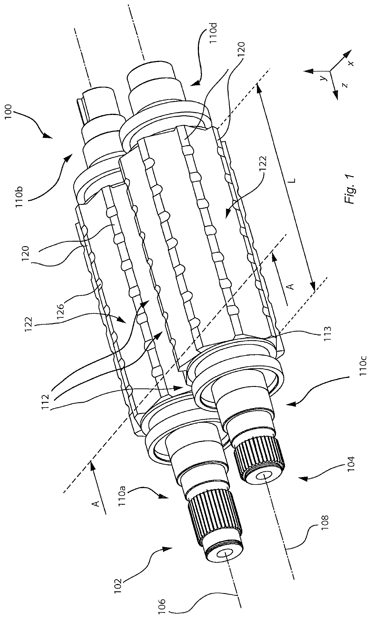
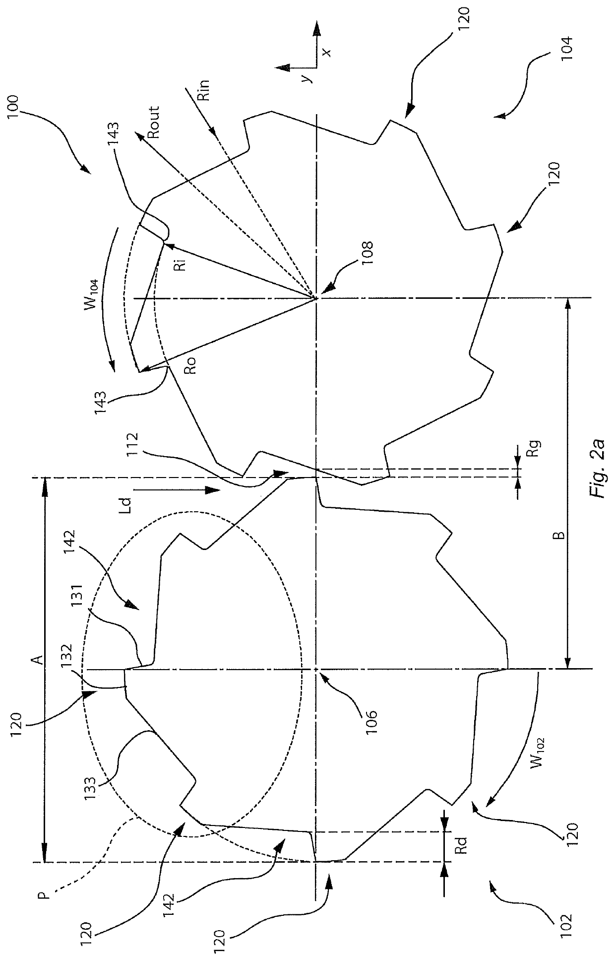
[0011]By “contactless” co-operation there is no direct contact between the two rollers, or interference between the two working surfaces between the co-operating rollers. This reduces the wear of the rollers and as well as the risk for the two rollers to be wedged with resulting breakdown of the driveline of the rollers. Another way to describe the co-operation is in a similar manner as a contactless interaction between a gear and a pinion. The meshed and contactless co-operation assures that there is always a gap, or space, between the rollers. When the container compressing arrangement compresses containers the containers are compressed so that they fill, or at least partly fill, the gap, or space between the two rollers.
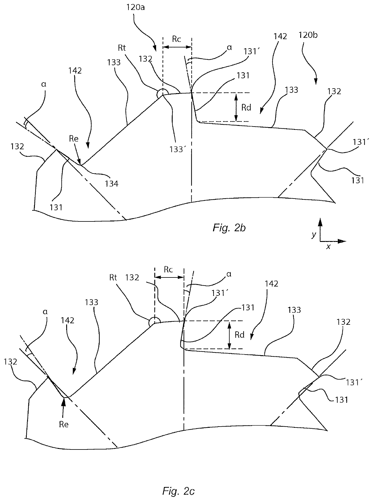
[0039]Additionally or alternatively, by rotating one of said rollers around said rotation axis, the width of said roller gap is adjusted. The roller gap may be adjusted by rotating one roller around the rotation axis, while the other roller is locked in place, i.e. the other roller not being rotated. This allows for the roller gap to be increased or decreased without changing the centre-to-centre distance of the rollers of the container compressing arrangement. This may be advantageous by the same container compressing arrangement being able to configure for compressing containers having different wall thickness. A reverse vending machine comprising the container compressing arrangement may thus be configurable for managing different regional restrictions in the world. The trailing ridges of the rollers may be arranged so that a linear, or almost linear, relationship is achieved between the amount of rotational adjustment, or rotating of one roller in respect to the other roller, and the roller gap width.

Problems solved by technology

The loads in turn result in mechanical wear which may results in mechanical and fatigue failure of the rollers.
This may be due to the material of the rollers failing, due to being too weak and not suited for use in rollers.
The failure may also be due to the design of a roller, leading to elevated local mechanical stresses where fatigue cracks can initiate and propagate until fatigue failure occurs in the roller.
Such failures are costly and results in downtime for the reverse vending machine.
However, such materials often have a high material cost compared to materials often used for rollers.
Using higher strength materials also increase roller manufacturing costs by the increased strength in the materials increasing manufacturing tool wear and manufacturing time.

Method used


Image

  • Container compressing arrangement
  • Container compressing arrangement
  • Container compressing arrangement

Examples


Embodiment Construction

[0060]In the present detailed description, exemplary embodiments of a container compressing arrangement according to the present invention are mainly discussed with reference to schematic views showing a container compressing arrangement according to various embodiments of the invention. It should be noted that this by no means limits the scope of the invention, which is also applicable in other circumstances for instance with other types or variants of container compressing arrangements or components than the embodiments shown in the appended drawings. Further, that specific components or features are mentioned in connection to an embodiment of the invention does not mean that those components cannot be used to an advantage together with other embodiments of the invention. The invention will now be described with reference to the enclosed drawings where first attention will be drawn to the structure, and secondly to the function. Like reference characters refer to like elements thr...


PUM


Abstract

Container compressing arrangement, mountable in a reverse vending machine, for compacting empty containers, in particular beverage bottles or cans which are preferably made of plastic or metallic material, such as PET or tinned metal, the container compressing arrangement including: a first and a second rotatable roller, each of the rollers having a working surface arranged between two oppositely arranged ends, wherein the rollers are arranged adjacent to each other to rotate in opposite directions around a respective rotation axis in a common geometrical xz-plane; and wherein the working surface includes a plurality of ridges extending across the working surface, in an axial direction of the roller, and distributed in the circumferential direction of the working surface, each ridge having a longitudinal extension in the axial direction.

Description

TECHNICAL FIELD OF THE INVENTION[0001]The present invention relates to a container compressing arrangement mountable in a reverse vending machine, as well as a method for compressing containers in a reverse vending machine.BACKGROUND[0002]Reverse vending machines are generally arranged so that a person can return empty containers, and in some cases receive some money in return. The reverse vending machine may collect a large number of containers in a short period of time. This means that the reverse vending machine needs to efficiently store the containers so that the storage bin for the containers need not be replaced too frequently. Therefore, the containers are compressed by the reverse vending machine so that they each take up less space than before being compressed.[0003]In order to compress the containers, the reverse vending machines typically have a compressing arrangement with rollers which have two main tasks, grabbing the container and then compressing it between the roll...

Claims


Application Information

Patent Timeline
Patent Type & Authority Patents(United States)
IPC IPC(8): B30B9/32G07F7/06B30B3/00
CPCB30B9/325B30B3/005G07F7/0609Y02W30/62
Inventor JENTER, HOLGERVÖLKLE, THOMAS
Owner TOMRA SYSTEMS
Learn More