Motor driving apparatus and method thereof

a technology of motor driving and control method, which is applied in the direction of dynamo-electric converter control, dynamo-electric gear control, dynamo-electric brake control, etc., can solve the problem of more complicated control of the operation of the motor

Active Publication Date: 2022-04-05
LG ELECTRONICS INC
View PDF7 Cites 0 Cited by
  • Summary
  • Abstract
  • Description
  • Claims
  • Application Information

AI Technical Summary

Benefits of technology

[0008]The present disclosure provides a motor driving apparatus and a control method thereof, which can expand an operation control area for an inverter, without using a flux weakening operating area, in a space vector pulse width variable control.
[0009]The present disclosure also provides a motor driving apparatus and a control method thereof, which can improve a harmonic distortion rate in a space vector pulse width variable control.
[0010]The present disclosure also provides a motor driving apparatus and a control method thereof, which improve the voltage utilization rate of an inverter, thus improving the output efficiency of the inverter and a motor.
[0011]The present disclosure also provides a motor driving apparatus and a control method thereof, which improve the voltage utilization rate of an inverter and minimize a weak field control, thus reducing an iron loss and a copper loss due to an increase in current.

Problems solved by technology

Particularly, when the case of detecting a current flowing through one shunt resistor and calculating the phase current of each phase flowing through the motor through calculation on the basis of the detected current, thus controlling the operation of the motor, as in related art 2 (Korean Patent Laid-Open Publication No. 10-2011-0030304), is compared with the case of using two or three shunt resistors, related art 2 is problematic in that the detection of the phase current of each phase flowing through the motor may be limited, and thereby it is more complicated to control the operation of the motor.

Method used


Image

  • Motor driving apparatus and method thereof
  • Motor driving apparatus and method thereof
  • Motor driving apparatus and method thereof

Examples


Embodiment Construction

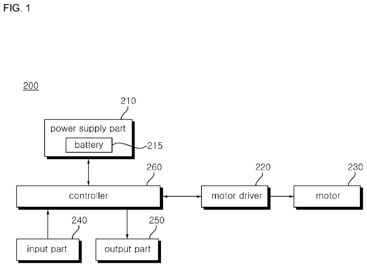
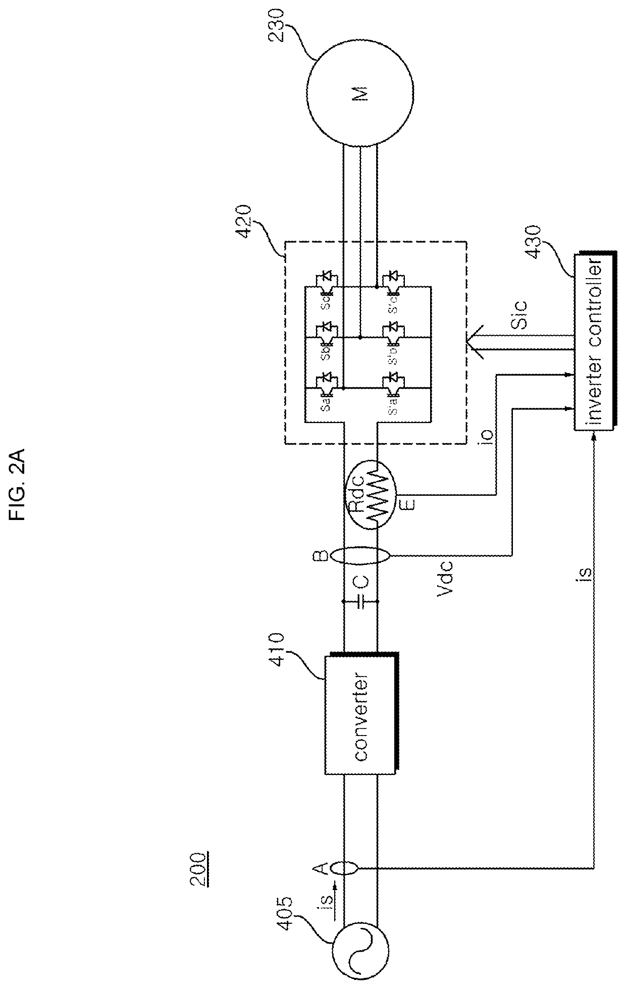
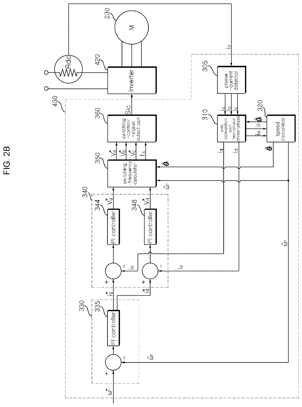
[0028]Hereinafter, the present disclosure will be described in detail with reference to the accompanying drawings. In order to clearly and briefly describe the present disclosure, components that are irrelevant to the description will be omitted in the drawings. The same reference numerals are used throughout the drawings to designate the same or similar components.

[0029]Terms “module” and “part” for elements used in the following description are given simply in view of the ease of the description, and do not carry any important meaning or role. Therefore, the “module” and the “part” may be used interchangeably.

[0030]It should be understood that the terms “comprise”, “include”, “have”, etc. when used in this specification, specify the presence of stated features, integers, steps, operations, elements, components, or combinations of them but do not preclude the presence or addition of one or more other features, integers, steps, operations, elements, components, or combinations there...


PUM


Abstract

A motor driving apparatus and a control method thereof, including a dc-link capacitor configured to store DC power, an inverter including a plurality of switching elements and converting the DC power stored in the dc-link capacitor into AC power to output the power to a motor, a dc-link resistor element disposed between the dc-link capacitor and the inverter; and a controller configured to control an operation of the inverter. The controller calculates a phase difference between a first reference voltage vector among a plurality of reference voltage vectors that are preset on the space vector and a voltage command, generates a switching frequency, determines a first operating point located in a dead band that is a one-phase current undetectable area in one switching cycle and a second operating point located at an outer position including a boundary of the dead band, and controls operation of the plurality of switching elements.

Description

CROSS-REFERENCE TO RELATED APPLICATIONS[0001]This application claims the priority benefit of Korean Patent Application No. 10-2019-0085059, filed on Jul. 15, 2019, the disclosure of which is incorporated herein by reference.BACKGROUND OF THE INVENTIONField of the Disclosure[0002]The present disclosure relates to a motor driving apparatus and a control method thereof and, more particularly, to a motor driving apparatus and a control method thereof, capable of increasing the voltage utilization rate of an inverter in a space-vector pulse width variable control, thus improving the efficiency of the inverter.Description of the Related Art[0003]A motor driving apparatus is an apparatus configured to drive a motor including a rotor which performs a rotary motion and a stator around which a coil is wound. The motor driving apparatus may be classified into a sensor type motor driving apparatus using a sensor, such as a hall sensor, and a sensorless type motor driving apparatus having no sen...

Claims


Application Information

Patent Timeline
Patent Type & Authority Patents(United States)
IPC IPC(8): H02P21/09H02P21/18H02P21/22H02P27/12
CPCH02P21/09H02P21/18H02P21/22H02P27/12H02P2201/13H02P6/18H02P27/08
Inventor MOON, JUNGSONGKIM, SEONGJULEE, DONGGEUN
Owner LG ELECTRONICS INC
Why Eureka
Try Eureka