
Fan device

a technology of fan device and fan body, which is applied in the direction of machines/engines, liquid fuel engines, instruments, etc., can solve the problems of large amount of heat generated, increased inner temperature of electronic devices, and affecting the performance of electronic devices

Active Publication Date: 2022-04-19
INVENTEC PUDONG TECH CORPOARTION +1
View PDF5 Cites 3 Cited by
  • Summary
  • Abstract
  • Description
  • Claims
  • Application Information

AI Technical Summary

Benefits of technology

Facilitates convenient assembly and disassembly of the fan device from the chassis, improving ease of use and maintenance by eliminating the need for screw-based assembly methods.

Problems solved by technology

During the operation of the electronic device such as personal computer or server, a large amount of the heat is generated.
When such heat is accumulated in the electronic device, the inner temperature of the electronic device is increased, which affects the performance of the electronic device or even causes the electronic device to shut down.

Method used


Image

  • Fan device
  • Fan device
  • Fan device

Examples


Embodiment Construction

[0010]In the following detailed description, for purposes of explanation, numerous specific details are set forth in order to provide a thorough understanding of the disclosed embodiments. It will be apparent, however, that one or more embodiments may be practiced without these specific details. In other instances, well-known structures and devices are schematically shown in order to simplify the drawing.

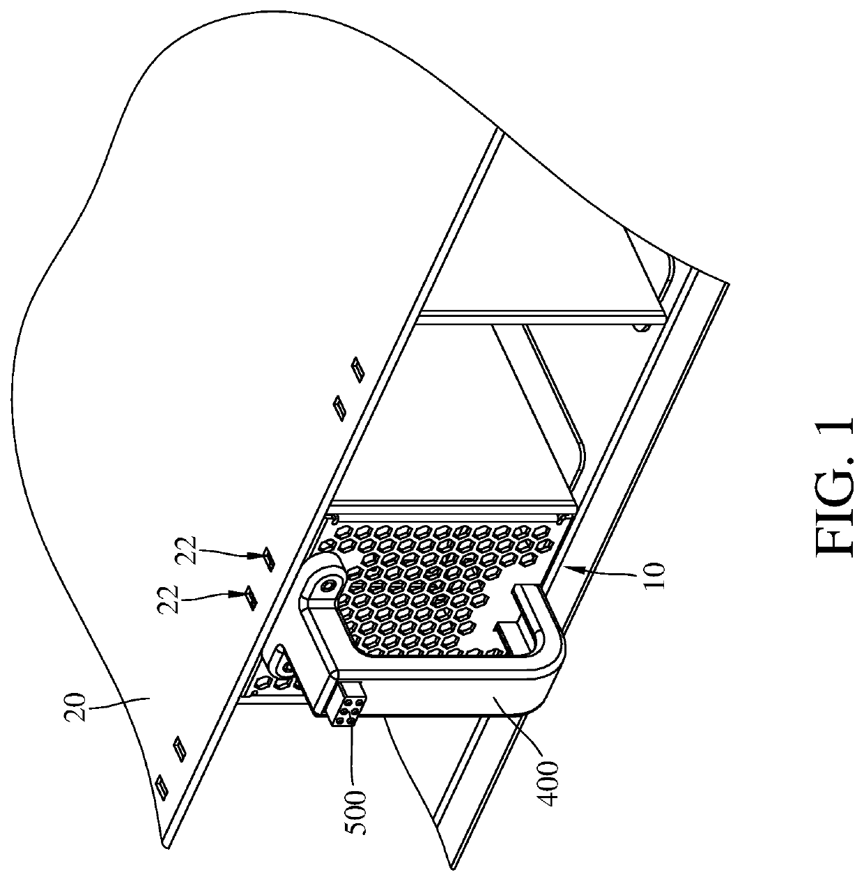
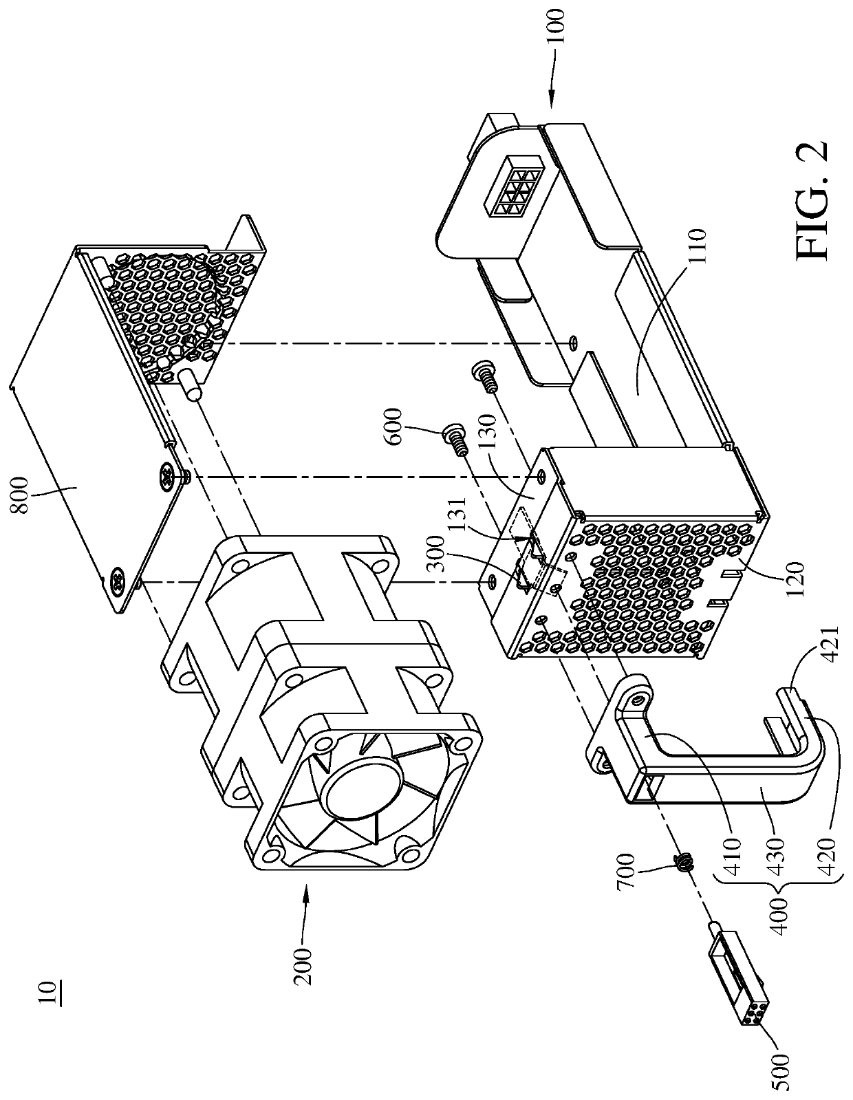
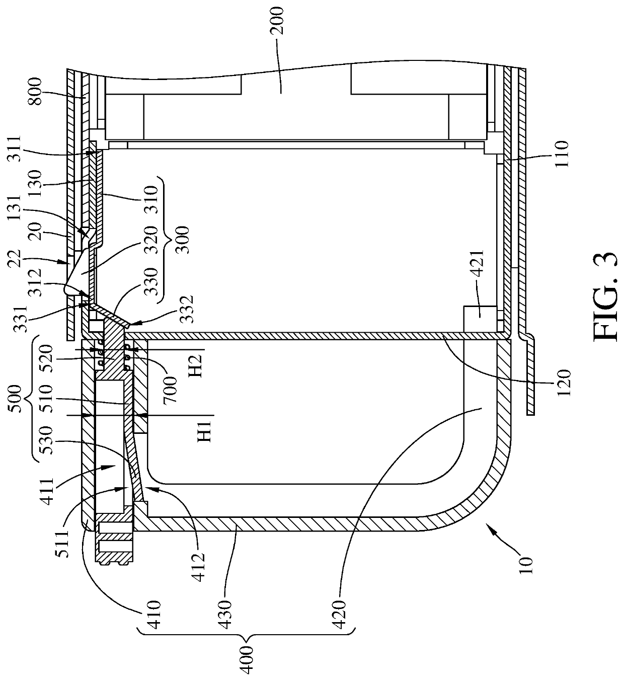
[0011]Please refer to FIG. 1 to FIG. 3, where FIG. 1 is a perspective view of a fan device according to a first embodiment of the invention, FIG. 2 is an exploded view of the fan device in FIG. 1, and FIG. 3 is a cross-sectional view of the fan device in FIG. 1.

[0012]This embodiment provides a fan device 10 configured to be mounted on a chassis 20 that has an engagement slot 22. The fan device 10 includes a casing 100, a fan 200, a clip 300, a handle 400, a trigger 500, a fastener 600, an elastic component 700 and a shield 800.

[0013]The casing 100 includes a bottom plate 110, a fron...


PUM


Abstract

A fan device configured to be assembled to chassis having engagement slot and including casing, fan, clip, handle, and trigger. Casing includes bottom plate, front plate and top plate. Top plate at least partially covers bottom plate and has through hole. Opposite sides of front plate are respectively connected to bottom plate and front plate. Fan is disposed on casing. Clip includes elastic part, engagement part and pressed part. Elastic part has fixed side and movable side that are opposite. Fixed side is disposed on top plate. Movable side is located closer to top plate than fixed side. Engagement part is connected to movable side. Engagement part is disposed through the through hole to be engaged with engagement slot. Pressed part is connected to movable side. Handle is disposed on front plate. Trigger is movably disposed on handle.

Description

CROSS-REFERENCE TO RELATED APPLICATIONS[0001]This non-provisional application claims priority under 35 U.S.C. § 119(a) on Patent Application No(s). 201910827540.X filed in China, on Sep. 3, 2019, the entire contents of which are hereby incorporated by reference.BACKGROUND OF THE INVENTIONTechnical Field of the Invention[0002]The disclosure relates to a fan device, more particularly to a fan device that can be assembled to a casing without using screws.Description of the Related Art[0003]During the operation of the electronic device such as personal computer or server, a large amount of the heat is generated. The amount of such heat is related to the operation duration and the performance of the electronic device. When such heat is accumulated in the electronic device, the inner temperature of the electronic device is increased, which affects the performance of the electronic device or even causes the electronic device to shut down. Therefore, a heat dissipation device, such as a fan...

Claims


Application Information

Patent Timeline
Patent Type & Authority Patents(United States)
IPC IPC(8): F04D29/64F04D29/40
CPCF04D29/646F04D29/40F05B2230/606F05B2230/61F05D2230/642F05D2230/68F04D25/08G06F1/20F04D19/007F04D29/601
Inventor HONG, SHI-MINCHEN, HAI TINGNIE, CHAO
Owner INVENTEC PUDONG TECH CORPOARTION
Learn More