
Suspension tilting module for a wheeled vehicle and a wheeled vehicle equipped with said suspension tilting module

a technology for suspension tilting and wheeled vehicles, which is applied in the direction of resilient suspensions, suspension arms, vehicle springs, etc., can solve the problems of many problems that have to be solved or overcome, the provision of tilting actuating means and/or devices adapted to adequately carry out the tilting function has revealed to be a very difficult task, and the electromechanical actuating means are still affected by several drawbacks

Inactive Publication Date: 2008-01-17
FONDAZIONE TORINO WIRELESS
View PDF10 Cites 97 Cited by
  • Summary
  • Abstract
  • Description
  • Claims
  • Application Information

AI Technical Summary

Benefits of technology

[0008] In particular, it is an object of the present invention to provide a suspension tilting module for a wheeled vehicle allowing it to overcome the problems affecting the prior art tilting modules and / or systems of the kind equipped with electromechanical actuating means.
[0009] A further object of the present invention is that of providing a suspension tilting module equipped with actuating means which do not require any mechanical link between the power source providing the tilting torque and the tilting mechanism.
[0010] Still another object of the present invention is that of providing a suspension tilting module equipped with actuating means comprising a power source adapted to provide the tilting torque wherein the power source may be positioned and / or disposed at some distance from the suspension module, thus allowing improvement in the overall layout of the vehicle implementing this suspension tilting module.

Problems solved by technology

However, in spite of all the advantages offered by tilting vehicles, the further development of these vehicles has revealed that several problems have still to be solved or overcome.
However, providing tilting actuating means and / or devices adapted to adequately carry out the tilting function has revealed to be a very difficult task.
Although there are evident advantages offered by electromechanical actuating means, it has to be appreciated that the electromechanical actuating means are still affected by several drawbacks.
For instance, when a large reduction ratio is required between the rotational displacement of the electric motor and the rotational displacement of the reduction gear, the overall dimensions and the volume of the reduction gear increase drastically, so that it becomes difficult to conveniently position the reduction gear inside the vehicle.
Accordingly, it becomes difficult to obtain a convenient layout of the vehicle.
Moreover, due to the mechanical link between the electric motor and the tilting mechanism, the electric motor and the reduction gearbox have to be positioned into proximity of the tilting mechanism resulting in the total allowable tilting angle being limited and / or reduced, so that the tilting function may in some cases will not be satisfactory.
Furthermore, a further drawback affecting the tilting vehicles equipped with an electromechanical tilting system relates to the fact that the overall mass and weight of the vehicle drastically increases, resulting in the tilting function being slowed down so that the vehicle is not tilted as quickly as required with corresponding problems arising, for instance in the case of emergency situations.
Moreover, the mechanical transmission may generate noise and / or vibrations resulting in a decreased driving comfort for the driver.
Finally, due to the overall dimensions and weight of the known electromechanical actuating means, it becomes impossible to provide emergency actuating means adapted to provide the needed actuating torque in the case of failure of the main actuating means so that the vehicle no longer behaves as a tilting vehicle.
Finally, regular inspections and / or maintenance operations are needed for the purpose of checking the mechanical transmissions, thus resulting in increasing overall maintenance costs for the vehicle.

Method used


Image

  • Suspension tilting module for a wheeled vehicle and a wheeled vehicle equipped with said suspension tilting module
  • Suspension tilting module for a wheeled vehicle and a wheeled vehicle equipped with said suspension tilting module
  • Suspension tilting module for a wheeled vehicle and a wheeled vehicle equipped with said suspension tilting module

Examples


Embodiment Construction

[0037] While the present invention is described with reference to the embodiments as illustrated in the following detailed description as well as in the drawings, it should be understood that the following detailed description as well as the drawings are not intended to limit the present invention to the particular illustrative embodiments disclosed, but rather that the described illustrative embodiments merely exemplify the various aspects of the present invention, the scope of which is defined by the appended claims.

[0038] As apparent from the disclosure given above, the present invention is understood to be particularly advantageous when used for applications in the automotive field; in particular, the present invention is understood to be particularly advantageous when applied to the steering wheels of vehicles. For this reason, examples with be given in the following in which corresponding embodiments of the tilting module and / or system according to the present invention are d...


PUM


Abstract

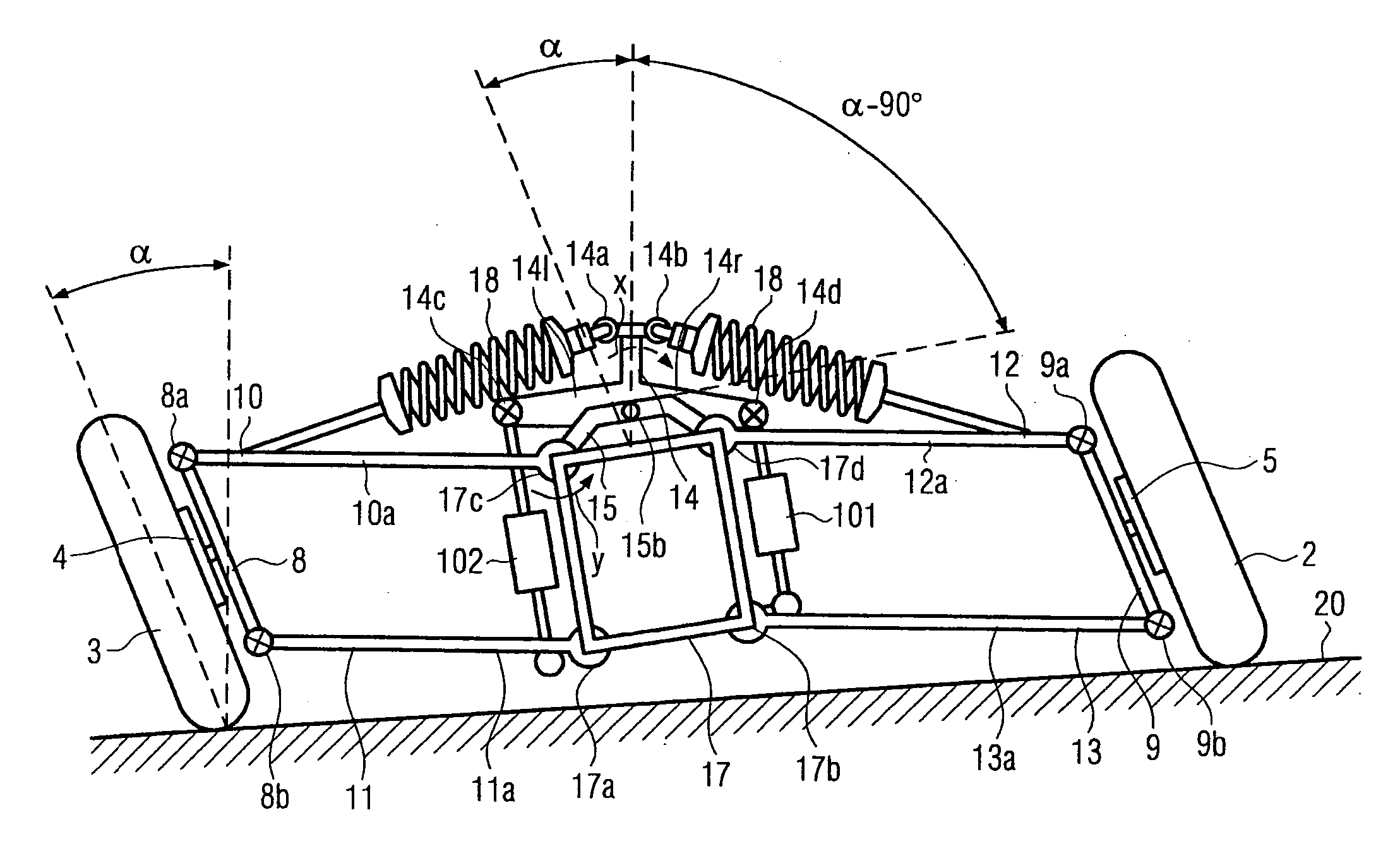
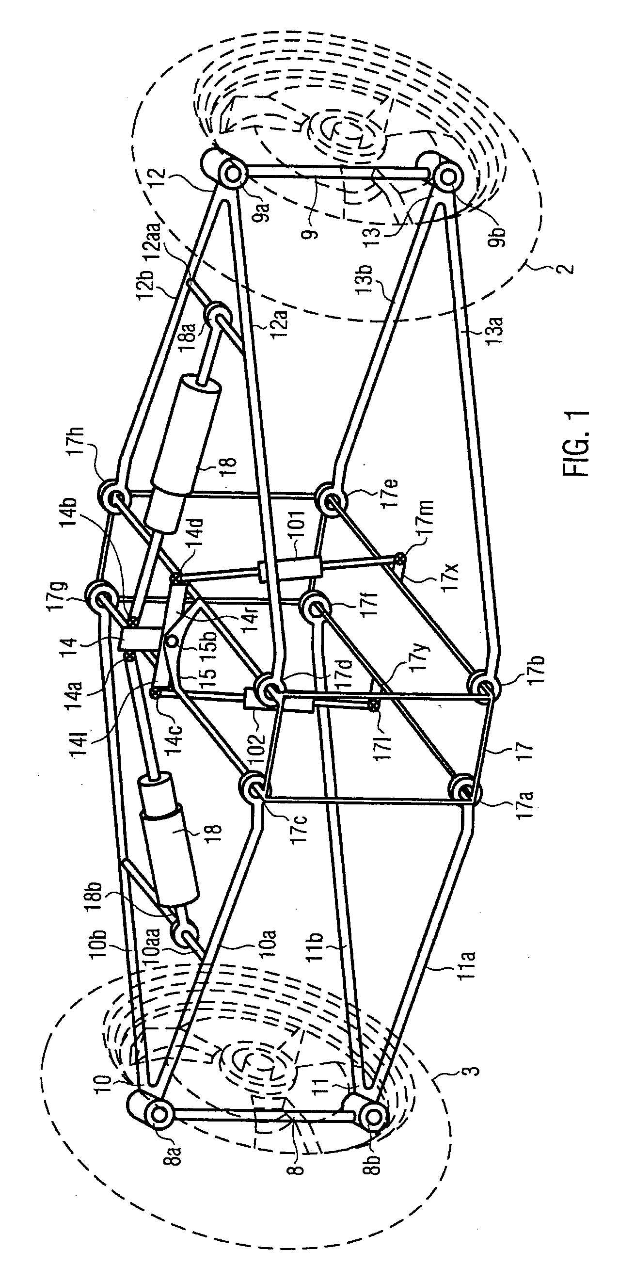
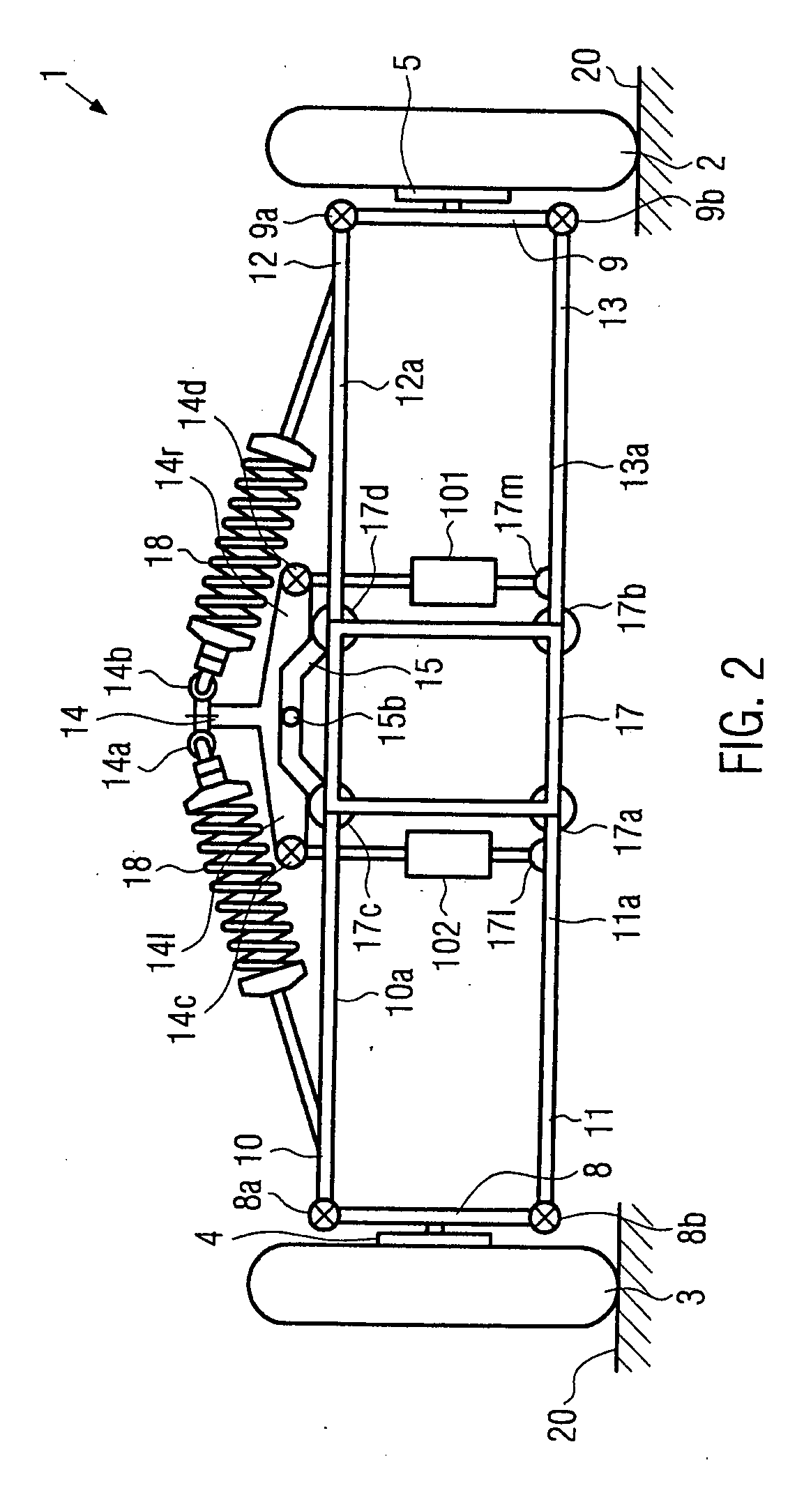
A tilting suspension system is provided for two wheels (2, 3) of a vehicle (200) disposed on a common axle with the module comprising a rigid frame (17) adapted to be firmly fixed to the chassis of the vehicle so as to be tilted together with the whole vehicle and a tilting arm (14) pivotally linked to the rigid frame. The tilting of the rigid frame is obtained as a result of the counter torque arising when activating hydraulic actuating means (101, 102) pivotally interposed between the tilting arm (14) and the rigid frame (17), with the tilting arm being pivotally connected to shock absorbers (18). The tilting module further comprises suspension arms (10, 11, 12, 13) pivotally connected to the rigid frame, with the suspension arms supporting, in cooperation with supporting uprights, the two wheels thus allowing both tilting and steering of the two wheels. The hydraulic actuating means (101, 102) are actuated by a hydraulic pump (112) driven by an electric motor (108).

Description

FIELD OF THE PRESENT INVENTION [0001] The present invention relates to the field of automotive applications. In particular, the present invention relates to a suspension tilting module for wheeled vehicles and a wheeled vehicle equipped with such a suspension tilting module. In more detail, the present invention relates to a suspension tilting module allowing at least two wheels of a vehicle disposed on a common axle to be tilted together with the whole body of the vehicle. Still in more detail, the present invention relates to a suspension tilting module allowing both tilting and vertical displacement of said two wheels. Furthermore, the present invention relates to a suspension tilting module allowing it to adequately absorb shocks to which one or both of the two wheels are subjected, for instance, when one or both of the two wheels crosses a bump. Still in more detail, the present invention relates to a suspension tilting module equipped with hydraulic actuating means adapted to ...

Claims


Application Information

Patent Timeline
Patent Type & Authority Applications(United States)
IPC IPC(8): B60G21/05
CPCB60G7/006B60G21/007B60G2200/144B60G2200/46B60G2202/413B62K5/10B60G2300/122B60G2300/45B60G2800/012B62D9/02B60G2204/421B60G21/073B60G2202/416
Inventor CARABELLI, STEFANOTONOLI, ANDREAFESTINI, ANDREACAVALLI, FABIO
Owner FONDAZIONE TORINO WIRELESS
Learn More