
Speed and torque optimizer for a drive train

a technology of speed and torque optimizer and drive train, which is applied in the direction of gear lubrication/cooling, gearing elements, gearing, etc., can solve the problems of excessive fuel consumption, severe engine and transmission strain, and unsuitable preset range of gear ratios, etc., and achieve the effect of easy reverse of the rotation direction of a given output sha

Active Publication Date: 2022-04-19
BROOKS EDDIE L +1
View PDF13 Cites 0 Cited by
  • Summary
  • Abstract
  • Description
  • Claims
  • Application Information

AI Technical Summary

Benefits of technology

The present invention is a device that improves the speed and torque of a drive train by using a larger input ring gear with more teeth than the output ring gear, which is mounted on the same shaft as the input gear. This results in a faster rotating output pinion gear, while minimizing torque loss. Additionally, the invention allows for easy reversal of the direction of rotation of the output shaft. The technical effects of the invention are increased speed and torque with minimal impact on torque and easy reversal of output shaft rotation.

Problems solved by technology

Most transmissions have a preset range of gear ratios that are not always suitable for certain applications.
Heavy-duty vehicles, such as pickup trucks and eighteen wheelers, are subjected to severe engine and transmission strain, excess fuel consumption and increased operating costs when the manufacturer's preset gear ratios are too high.

Method used


Image

  • Speed and torque optimizer for a drive train
  • Speed and torque optimizer for a drive train
  • Speed and torque optimizer for a drive train

Examples


Embodiment Construction

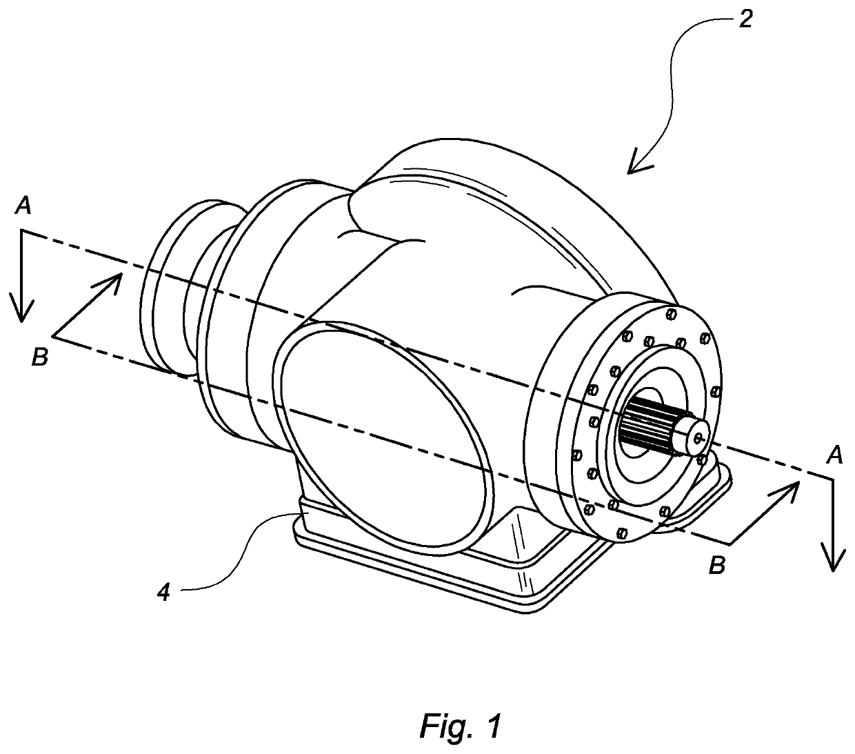
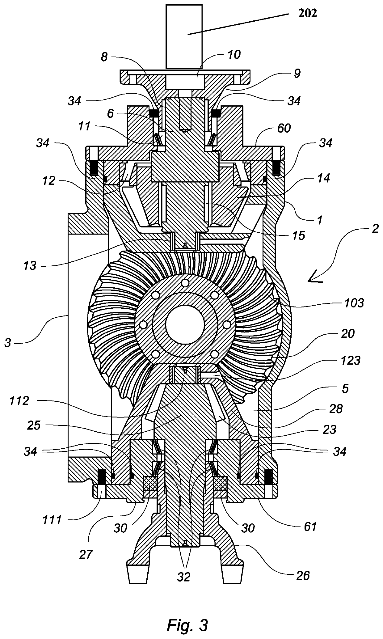
[0017]The present invention relates to a speed and torque optimizer for a drive train comprising a hollow housing 2 having a top wall 1, a removable bottom wall 3, a front wall 60, a rear wall 61, a plurality of sidewalls 4 and an interior chamber 5. The bottom wall may include apertures to provide cooling air to the interior chamber. As depicted in FIG. 1, the housing may be a unitary enclosure of any size or shape including contoured, rectangular, irregular, etc. The top wall 1 may also be removable to provide selective access to the interior components.

[0018]An opening on the front wall receives an input shaft 6 operably connected to a primary driver 202, such as the output shaft of a vehicle's transmission, a combustion engine, a blower motor or similar rotational driver. A flange 9 is connected to the primary driver, and also to the input shaft using a splined connection joint 8 and / or one or more bolts 10.

[0019]Received within the housing and secured to the distal end of the i...


PUM


Abstract

A speed and torque optimizer for a drive train includes an input shaft coupled with a primary driver having a pinion gear thereon that engages an input ring gear. The input ring gear is affixed to a first end of a carrier shaft having an output ring gear on an opposing end. The output ring gear engages an output pinion gear mounted on an output shaft. The input ring gear is larger in diameter than the output ring gear and therefore has more teeth. Because the input and output ring gears are mounted on the same shaft, they rotate at the same speeds thereby rotating the output pinion gear at a faster speed than the input pinion gear. The intermeshing gear teeth have a predefined curvature, pitch diameter and length to further accomplish increased speed at the output shaft while minimizing torque loss.

Description

CROSS REFERENCE TO RELATED APPLICATIONS[0001]This application is a continuation-in-part of application Ser. No. 15 / 998,272 filed on Jul. 26, 2018, the specification of which is incorporated herein by reference.BACKGROUND OF THE INVENTION[0002]The present invention relates to a device for improving the efficiency of power-transfer systems in vehicles or other mechanical drives.DESCRIPTION OF THE PRIOR ART[0003]Most mechanical drives include gearing systems that convert a higher engine speed to a lower output speed. For example, vehicle engines operate at rotational speeds that are higher than ideal for starting, stopping or routine driving. A transmission converts the engine's higher rotational speed to a lower output speed to rotate a drive shaft at a slower speed while increasing torque. The transmission allows the vehicle to accelerate from rest to a maximum speed, while maintaining engine efficiency. Most transmissions have a preset range of gear ratios that are not always suitab...

Claims


Application Information

Patent Timeline
IPC IPC(8): F16H1/20F16H57/02F16H57/038F16H37/04F16H57/04F16H57/021
CPCF16H1/203F16H37/041F16H57/021F16H57/038F16H57/0409F16H57/0495F16H1/222
Inventor BROOKS, EDDIE L
Owner BROOKS EDDIE L
Learn More